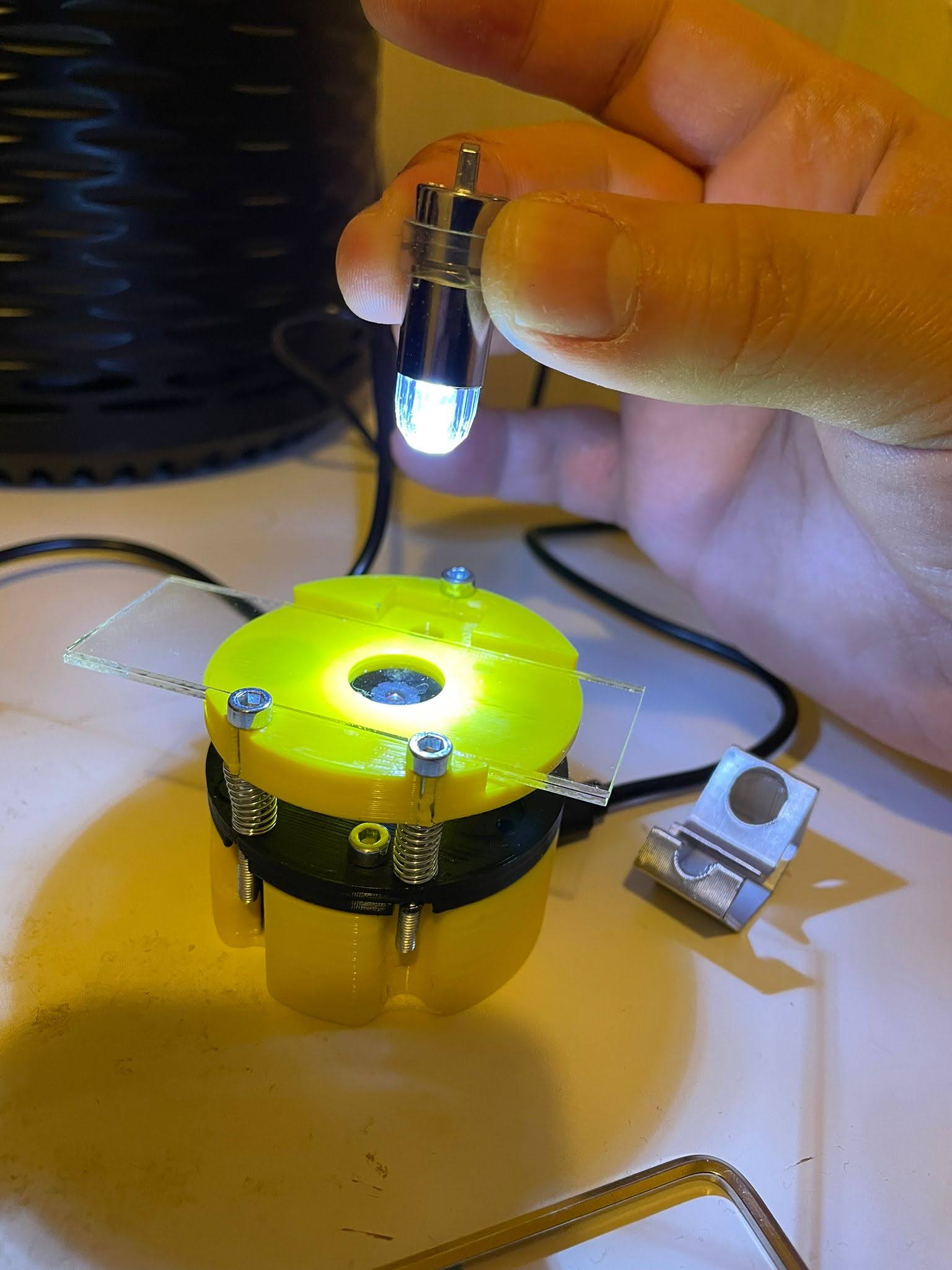
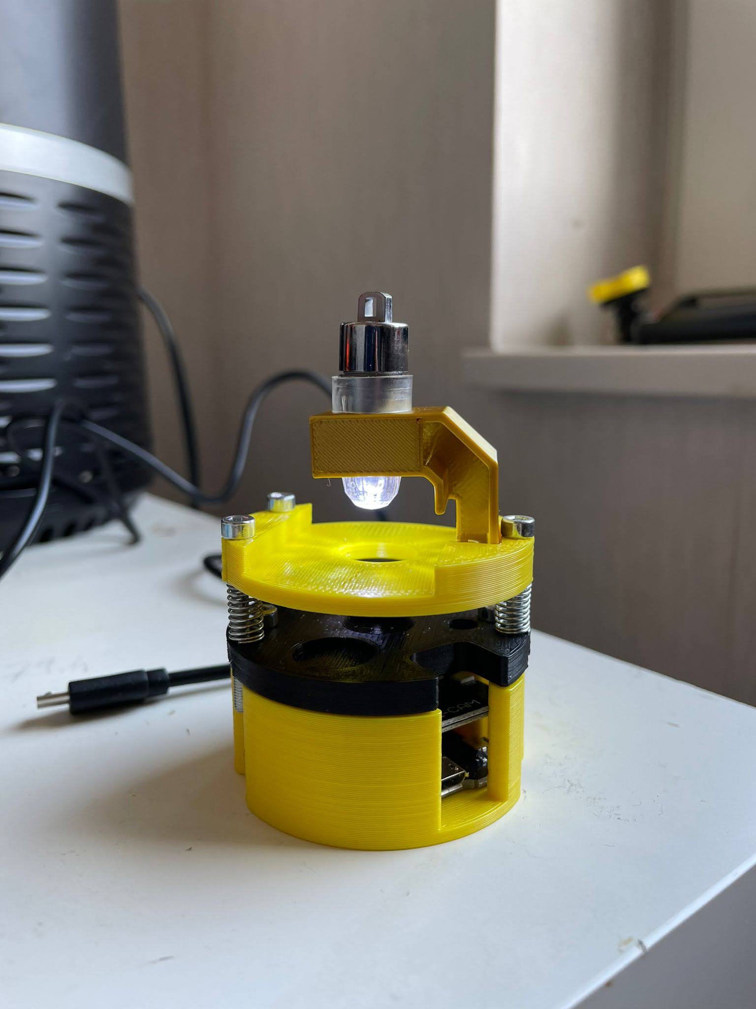
ESPressoscope (Injection Molded Version of the Matchboxscope)
A Cup-sized microscope that never sleeps.
This is the latest version of the base assembly for any ESP32-based microscope.
It is always advisable to first flash the software and then build the microscope around it.
Improvements
This device is a work-in-progress instrument. Not everything is perfectly working yet. Bare with us. If you find something sneaky, please feel free to file an issue or start a discussion here: https://github.com/matchboxscope/Matchboxscope
Known Issues:
- Hole for led holder larger
- Do we really want threaded inserts?
- Case of ESP32 may be pushing the boot/reset button causing issues while turning on?
Improvements:
- removing threaded inserts saves a hot iron, but removes smooth operation while focussing
- one of the insert holes is a little off, does not have enough printing material/support
- make hole round assembly larger in diameter to have moroe support for the threaded inserts?
- diffuser for the led
The newest 3D Printing files can be found in the ESPressoscope release here: https://github.com/Matchboxscope/Matchboxscope/releases/tag/v2
Flash the firmware
Please visit the following explanation Firmware
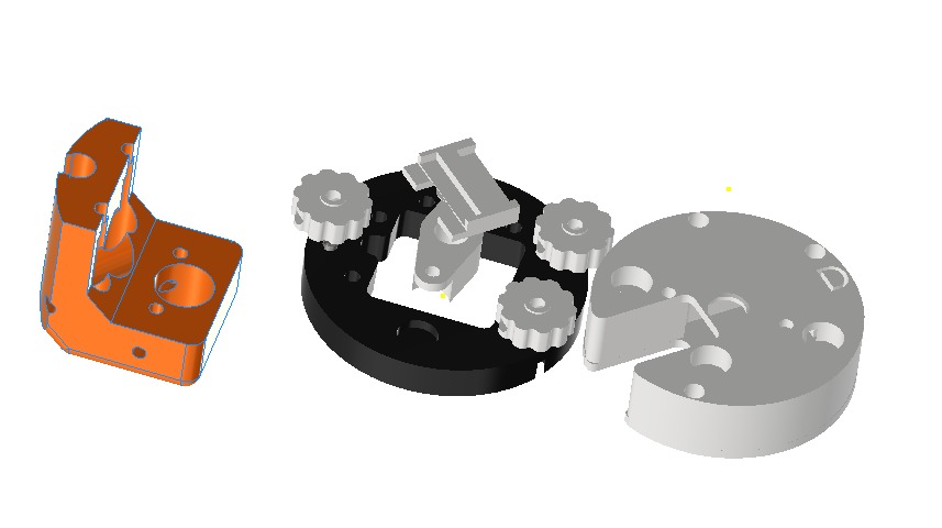
Assembly
These are the parts you need to build a Matchboxscope:
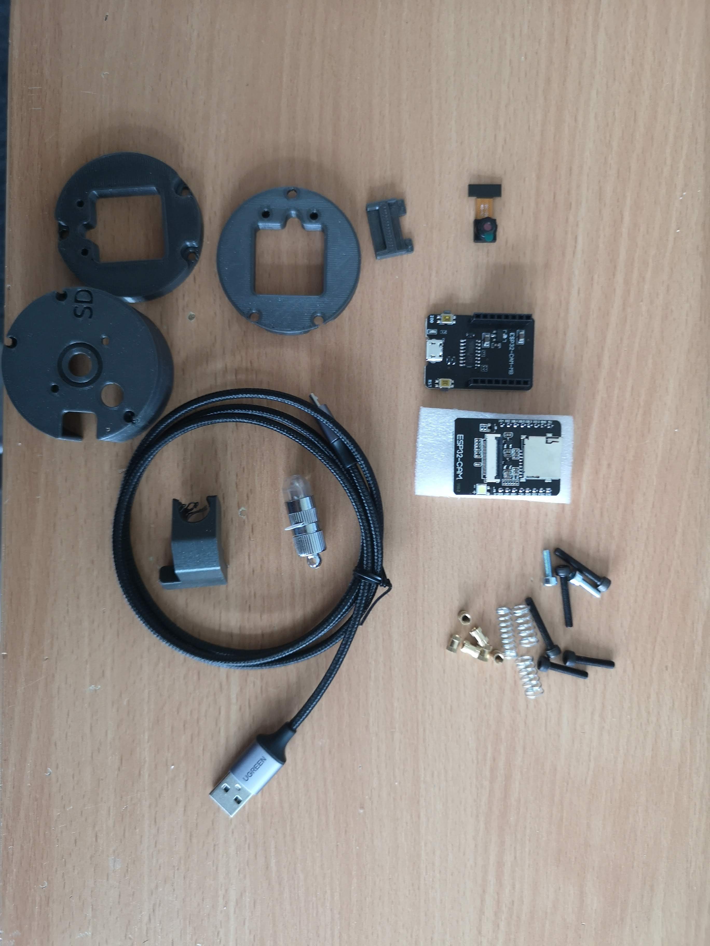
| Name | Description | Amount | Price (USD) | URL |
|---|---|---|---|---|
| ESP32-Camera board + USB Serial adapter | ESP32 Camera Board with USB Serial | 1 | $20 | Link |
| Lid/bottom (printed) | 3D Printed Lid/bottom | 2 | $2 (each) | Link |
| Base (printed) | 3D Printed Base | 2 | $2 (each) | Link |
| Camera holder (printed) | 3D Printed Camera holder | 1 | $3 | Link |
| Lamp holder (printed) | 3D Printed Lamp holder | 1 | $2 | Link |
| Lens holder (printed) | 3D Printed Lens holder | 1 | $2 | Link |
| LED Lamp | LIHAO Mini LED Lamp (Waterproof) | 1 | $5 | Link |
| Springs | Pack of 3 Springs | 3 | $1 (pack) | Link |
| M3x20 Cylindrical Headed Screws (DIN912) | Pack of 8 M3x20 Screws | 8 | $0.5 (pack) | Link |
| M3x6mm Screws (DIN912) | Pack of 2 M3x6mm Screws | 2 | $0.2 (pack) | Link |
| M3x12mm Screws (DIN912) | Pack of 4 M3x12mm Screws | 4 | $0.3 (pack) | Link |
| M3x24mm Screws (DIN912) | Pack of 3 M3x24mm Screws | 3 | $0.4 (pack) | Link |
| M3 threaded inserts (4x6mm) | Pack of 6 M3 Threaded Inserts | 6 | $1 (pack) | Link |
| USB micro cable | USB Micro Cable | 1 | $5 | Link |
WARNING: It is advisable to have the USB cable disconnected from the camera board. This way the USB connector won't rip off the PCB and you won't induce any electro static discharges which may ultimatively destroy the board
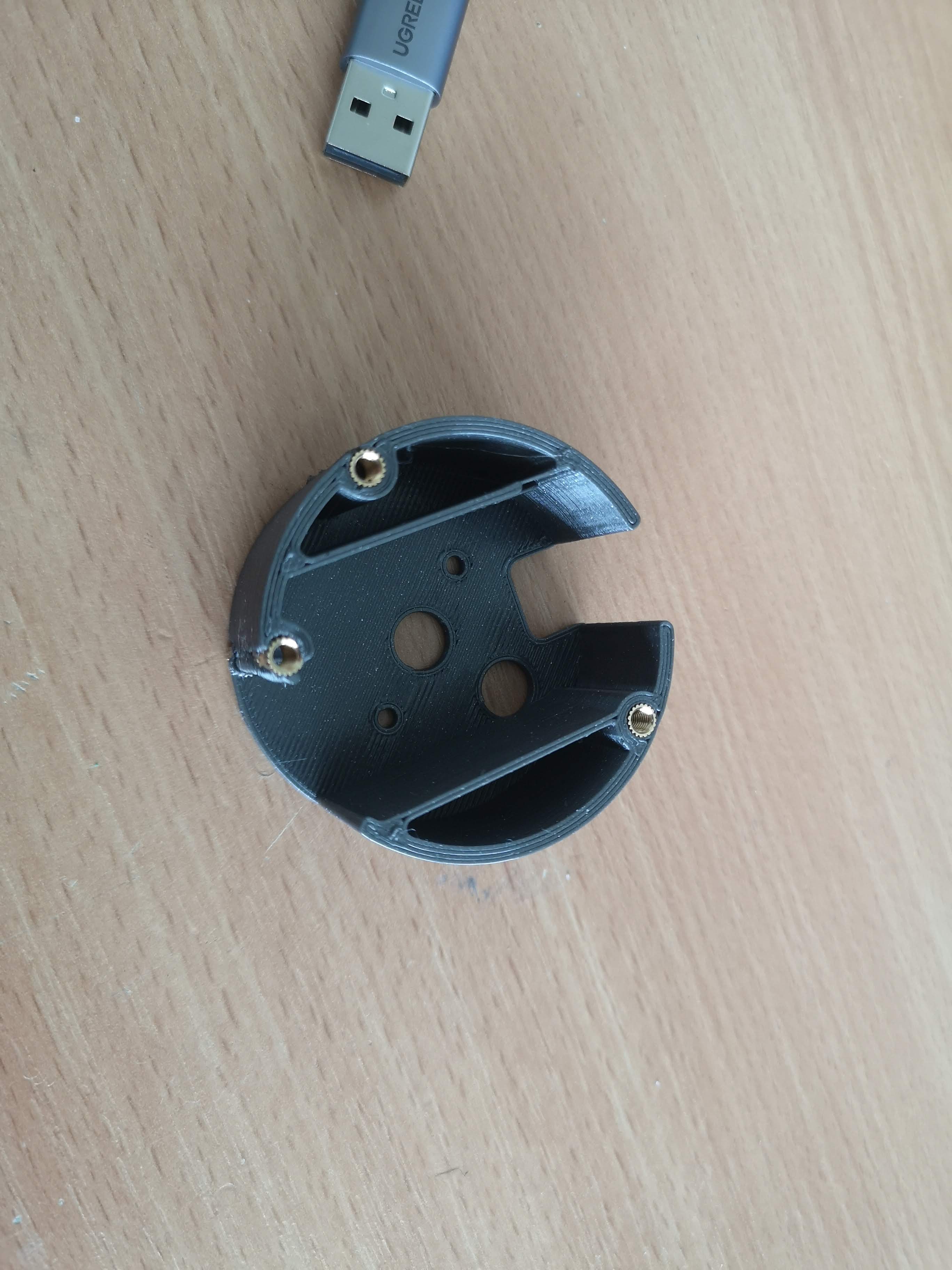
Add the threaded inserts to the base using a hot iron - don't burn yourself! Hint: You can have 3 inserts on the top and three on the bottom. A hot iron with a fine tip is better than one with a flat one. (HINT: This mechanism may change back to a non-threaded insert based version for better operatibility)
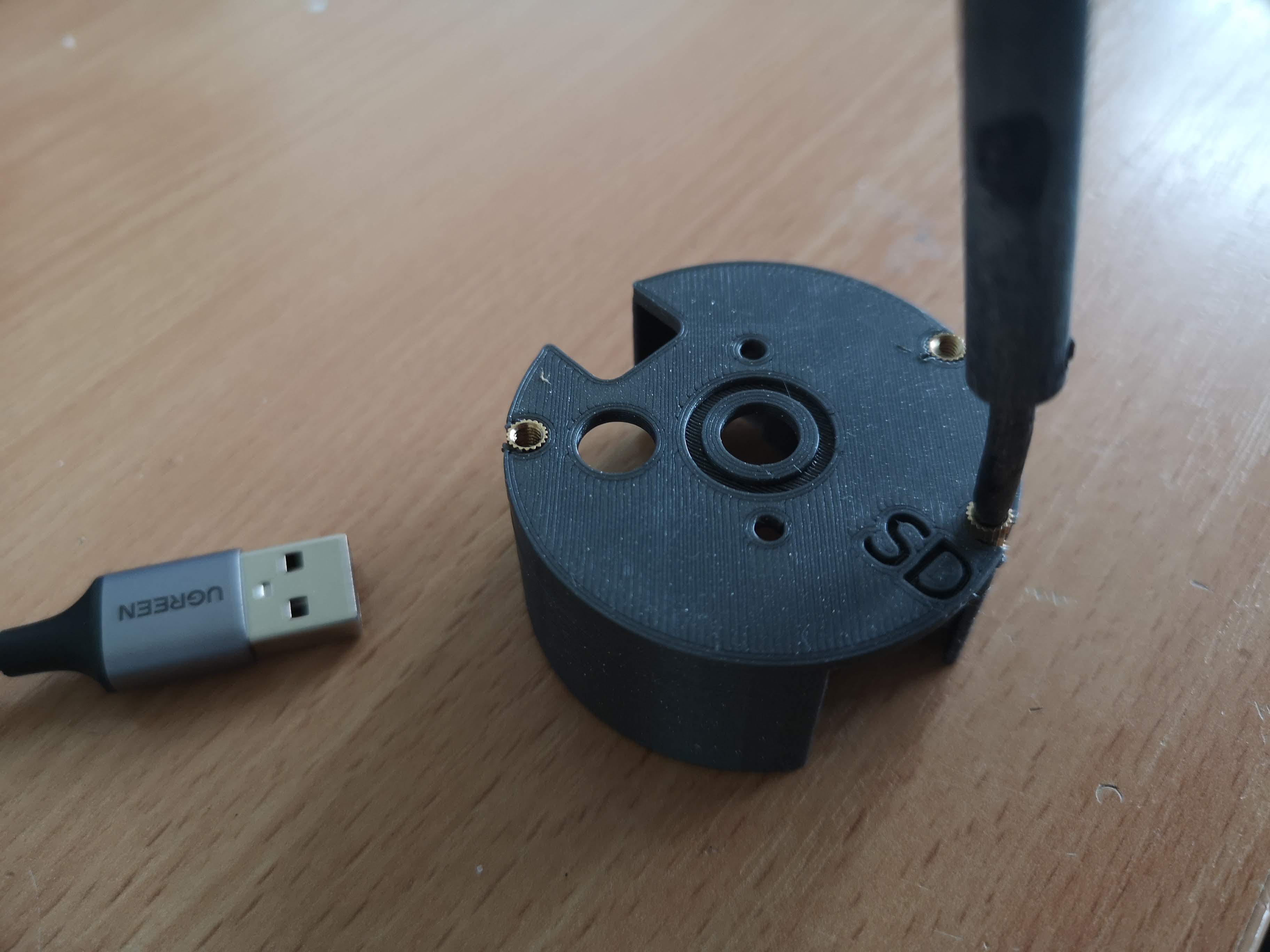
Repeat this for all 6 slots (or 5 if you only use 2 on the bottom)
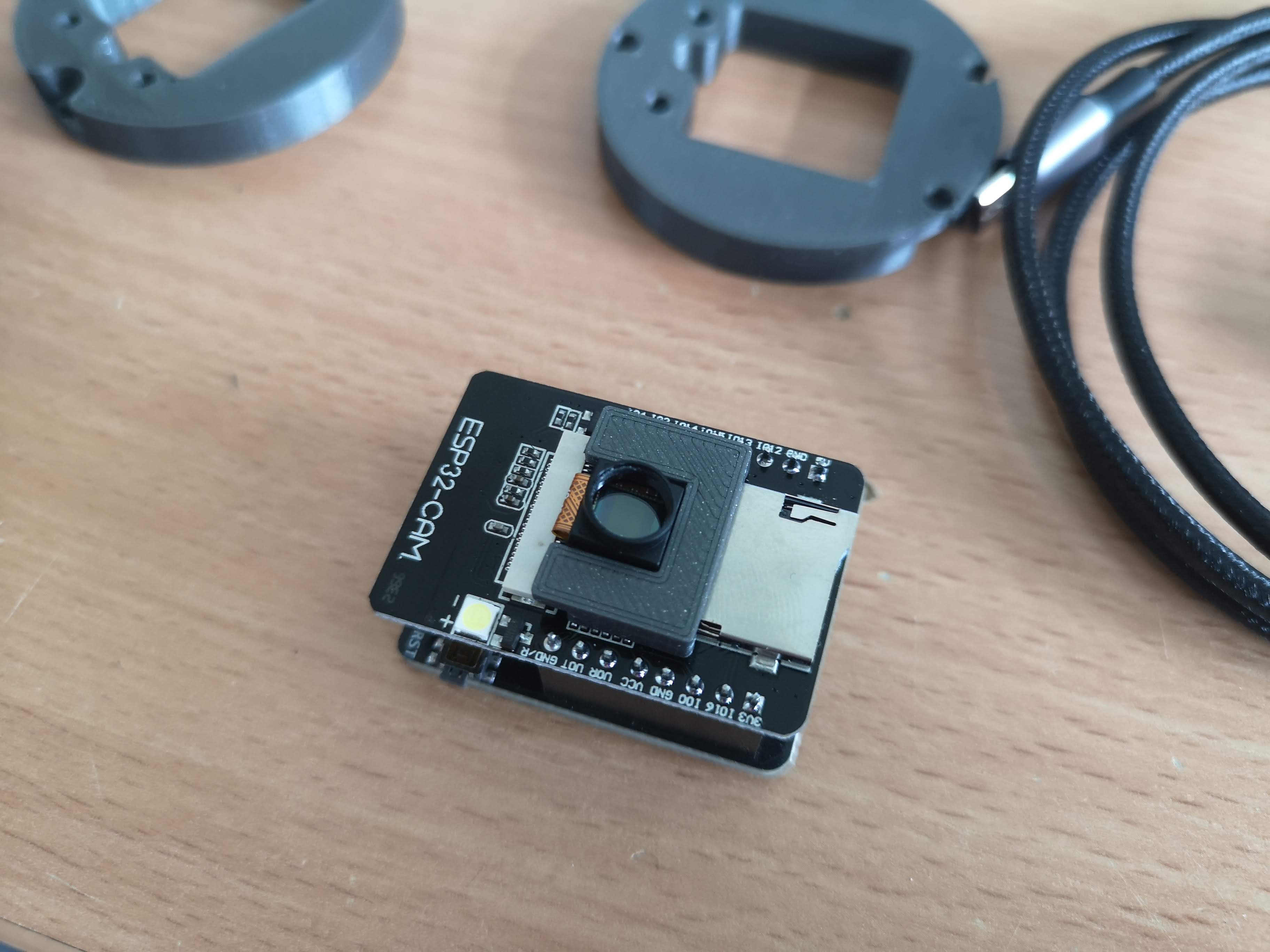
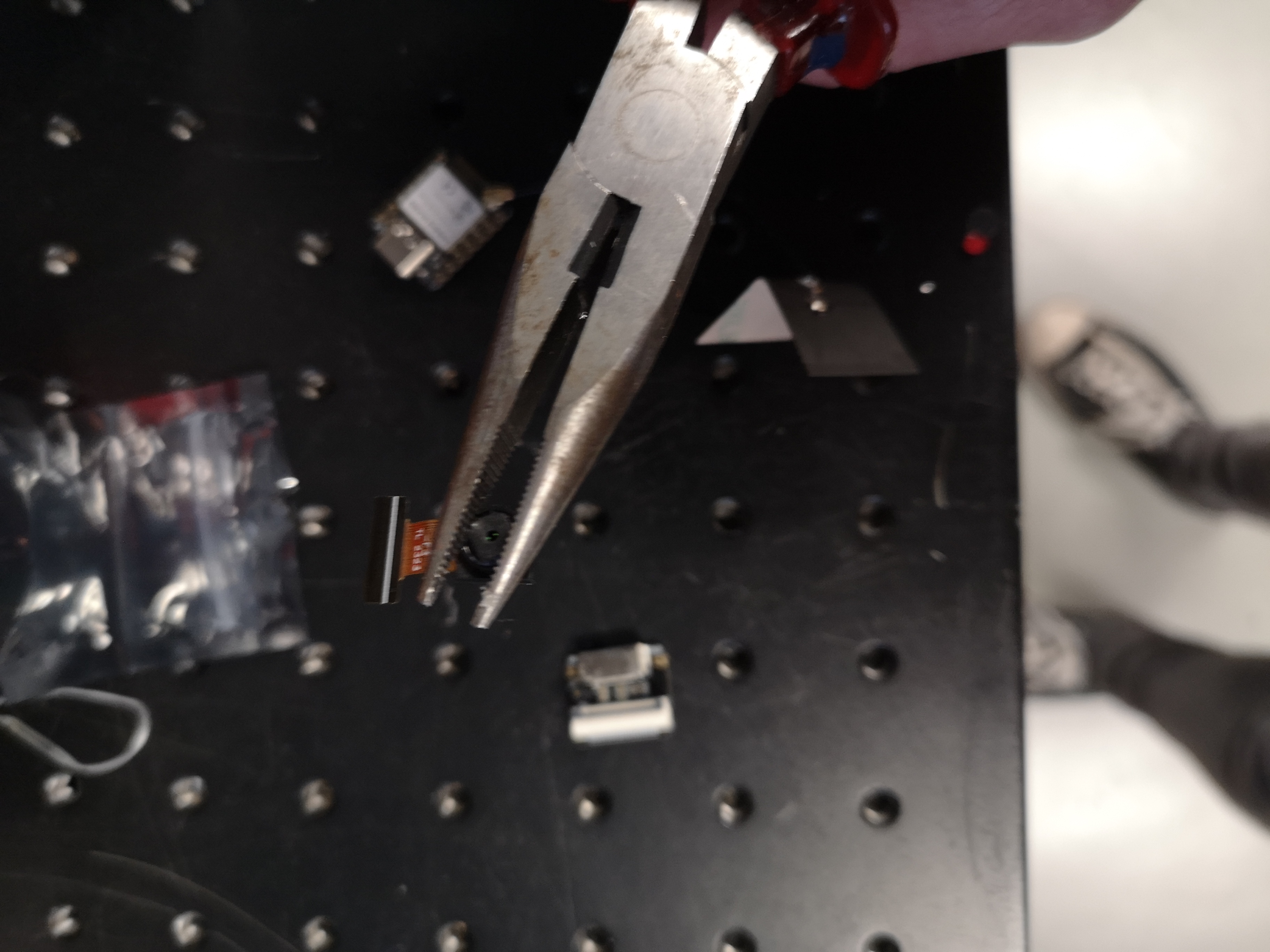
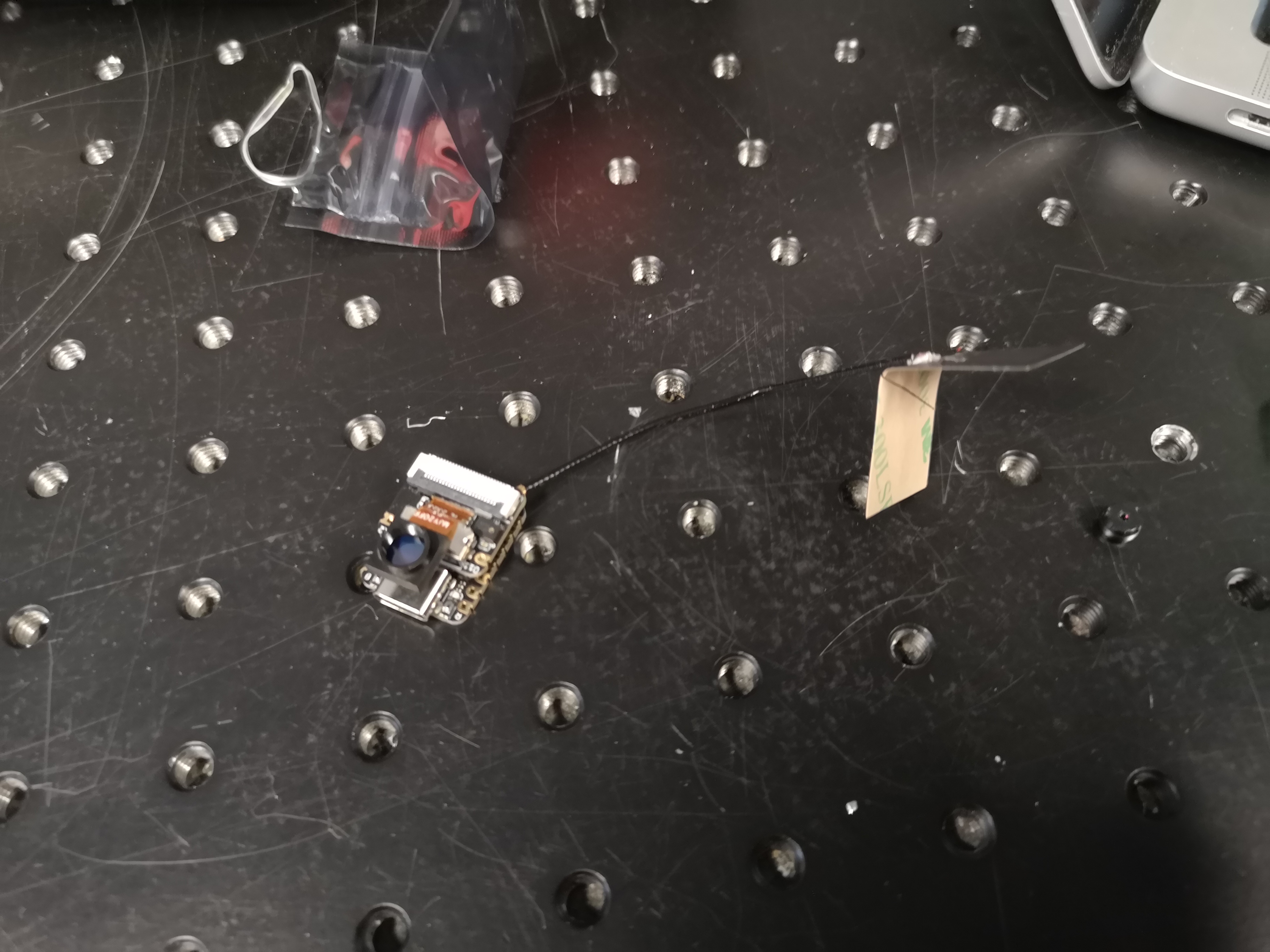
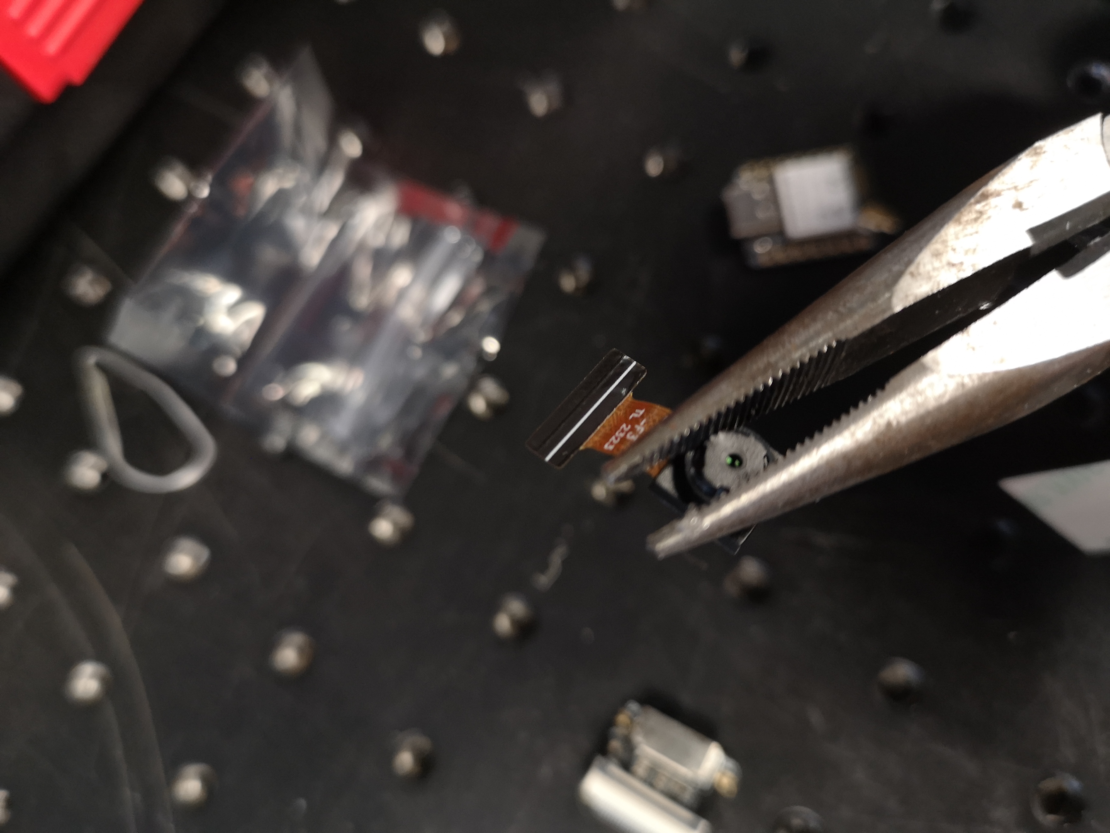
Remove the lens from the camera module using pliers
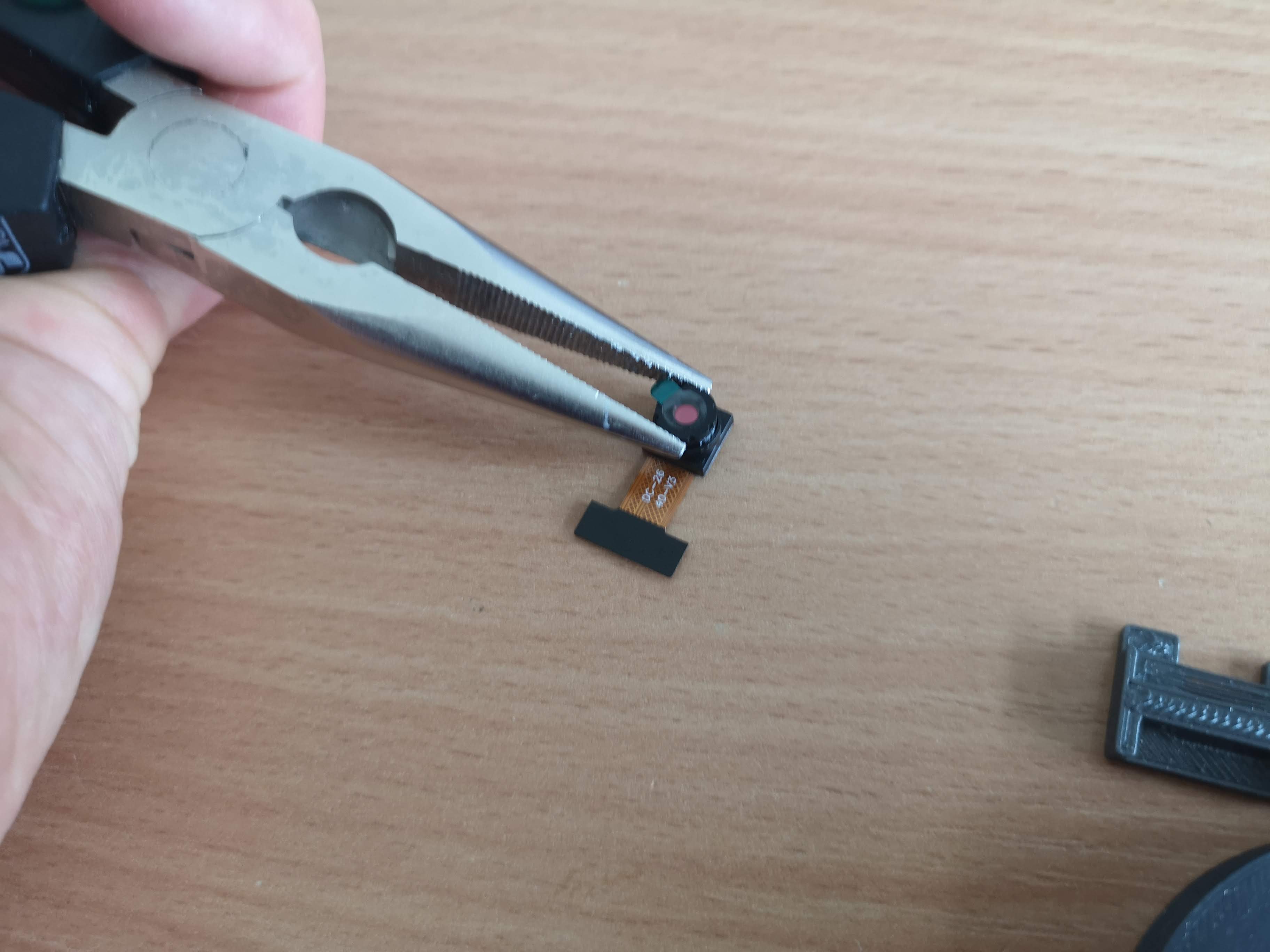
HINT/Warning: Be careful while removing the lens. The flex cable is sensitive to tension. It may be easier to first remove the camera module using the snap-bar mechanism and then later add it again.
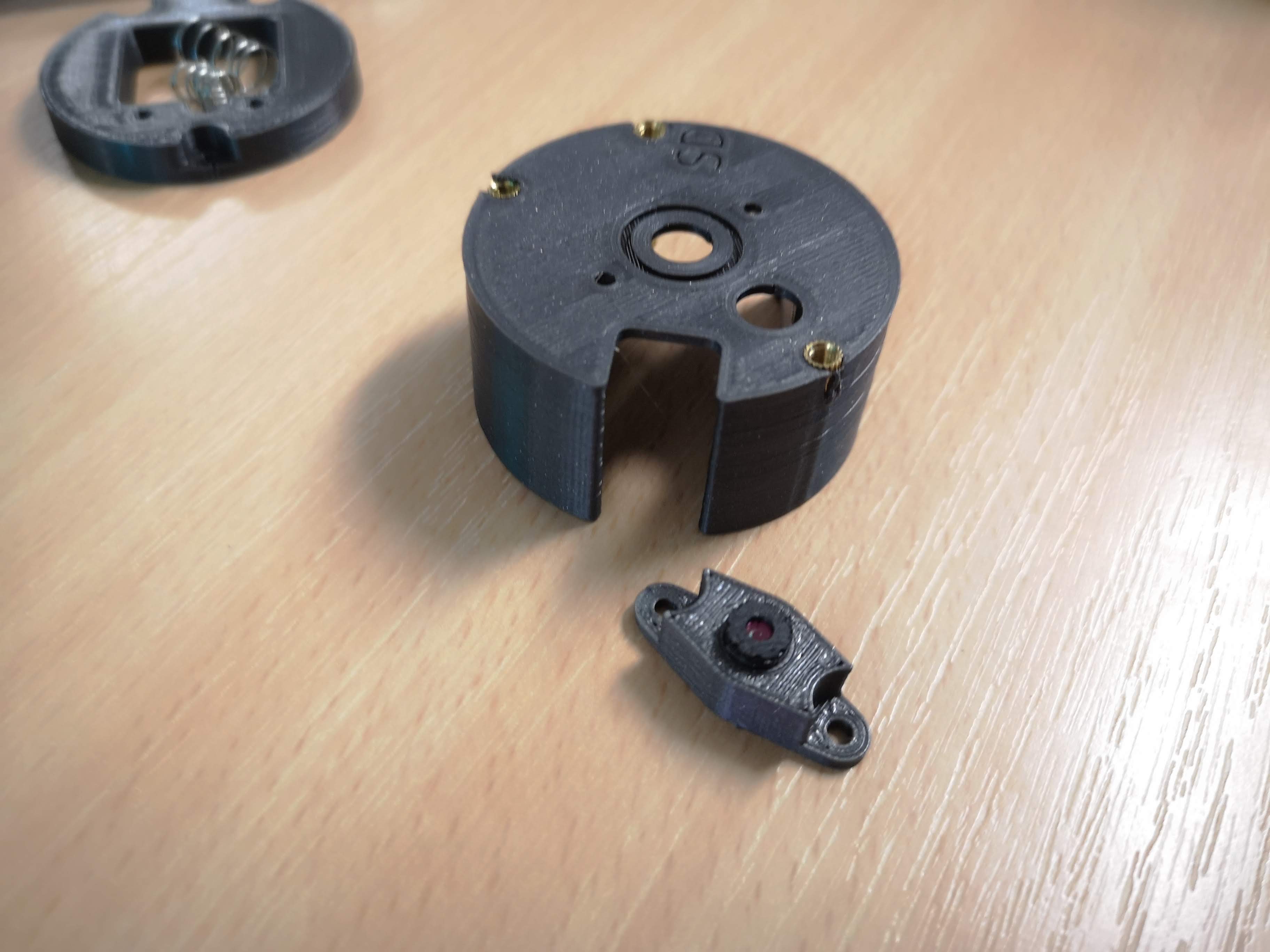
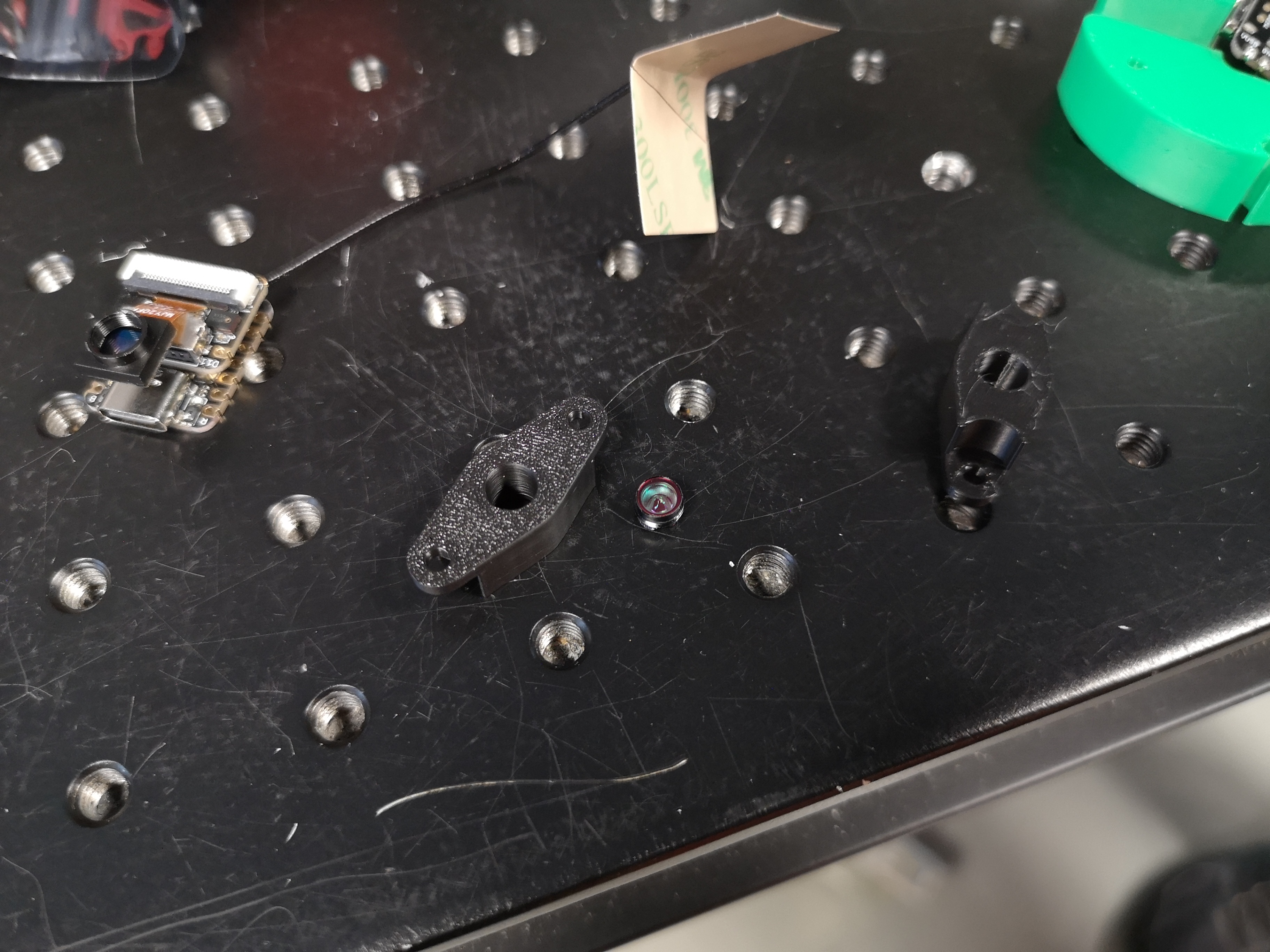
- Add the lens to the holder and remove the sticky tape (Note: This part looks a little different now since the screw has to move closer to the base board); Hint: The distance between the camera lens and the sensor determines the magnification, the further out the lens lurkes, the higher the magnification. You can tune it freely. Hint : Remove any sticker that may remain on the camera lens.
HINT: In Motion:
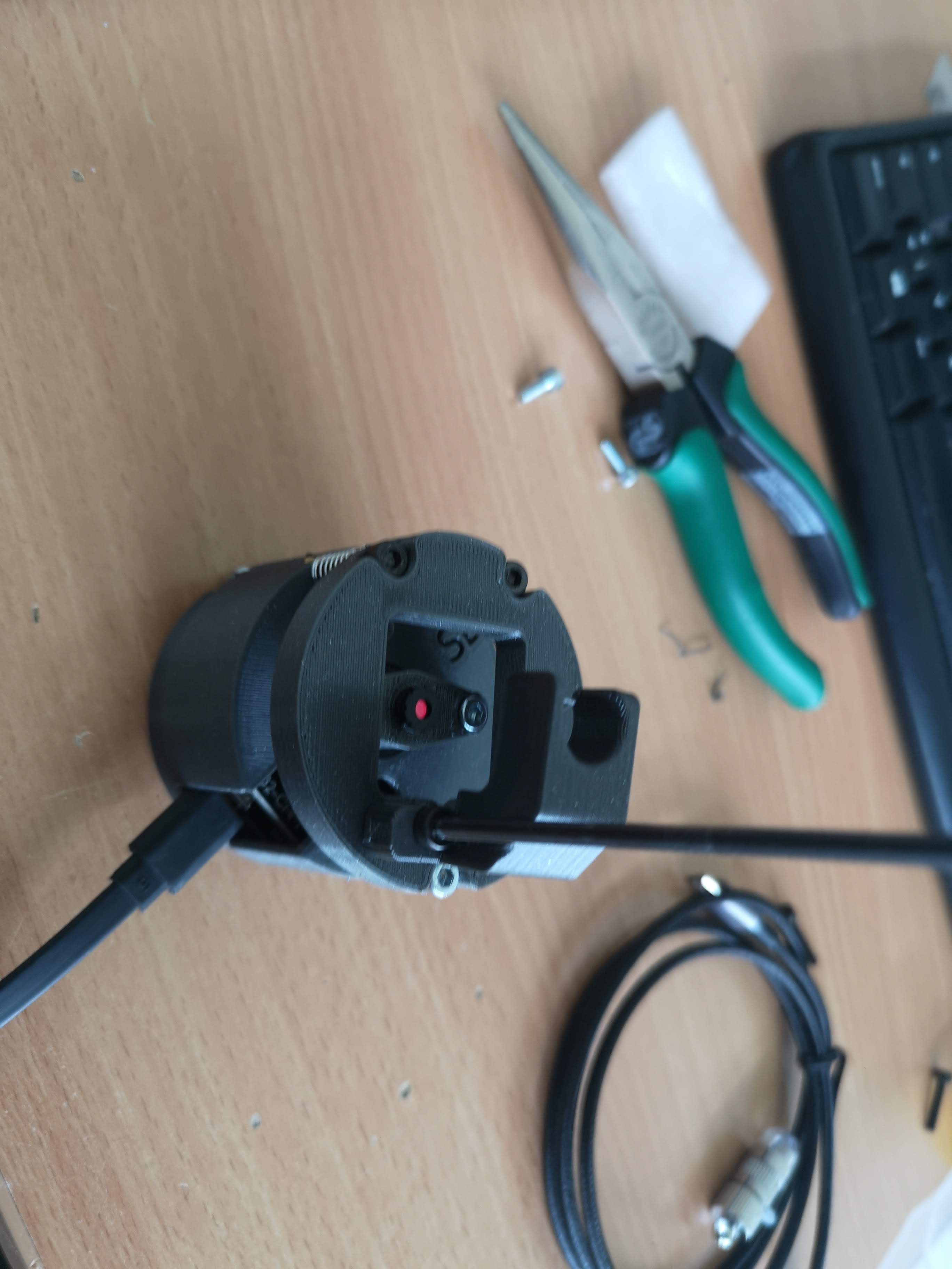
Fix the lens on the base using M3x6mm screws (Note: The screws should not touch the PCB later when everything is fully assembled! Therefore, please use short screws. )
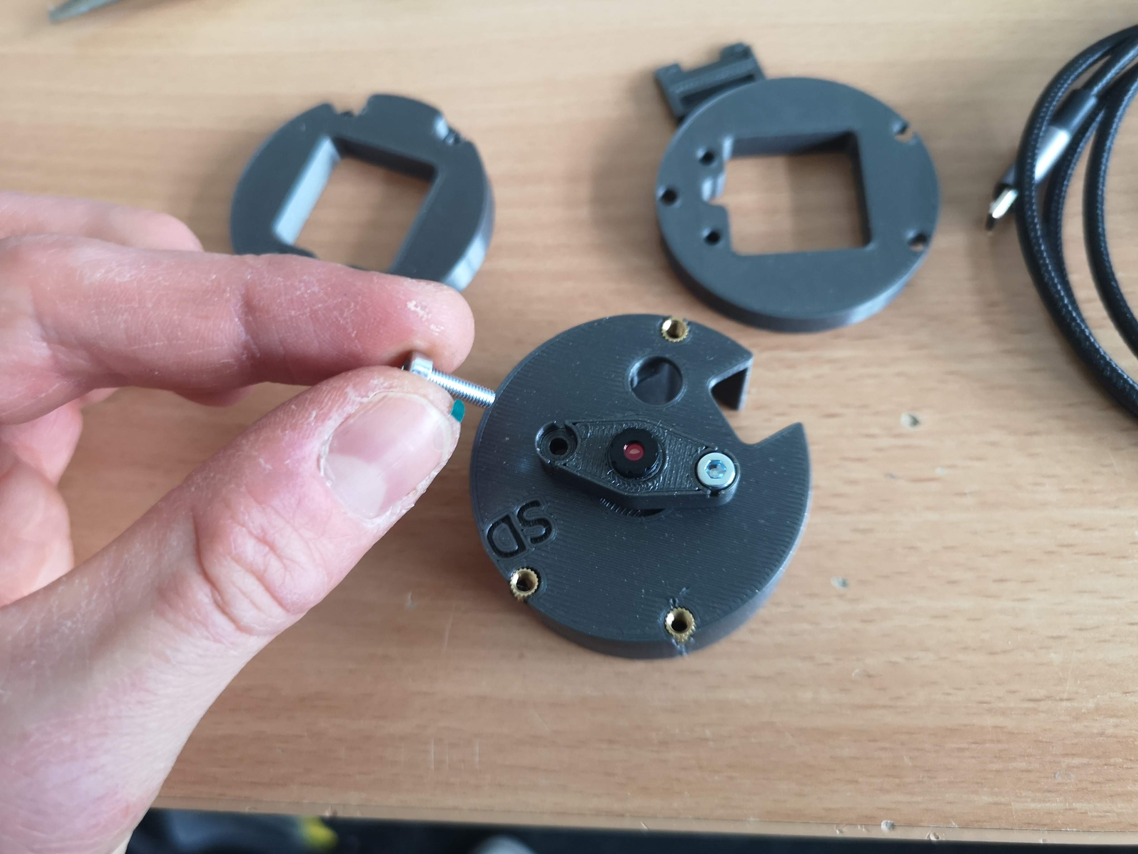
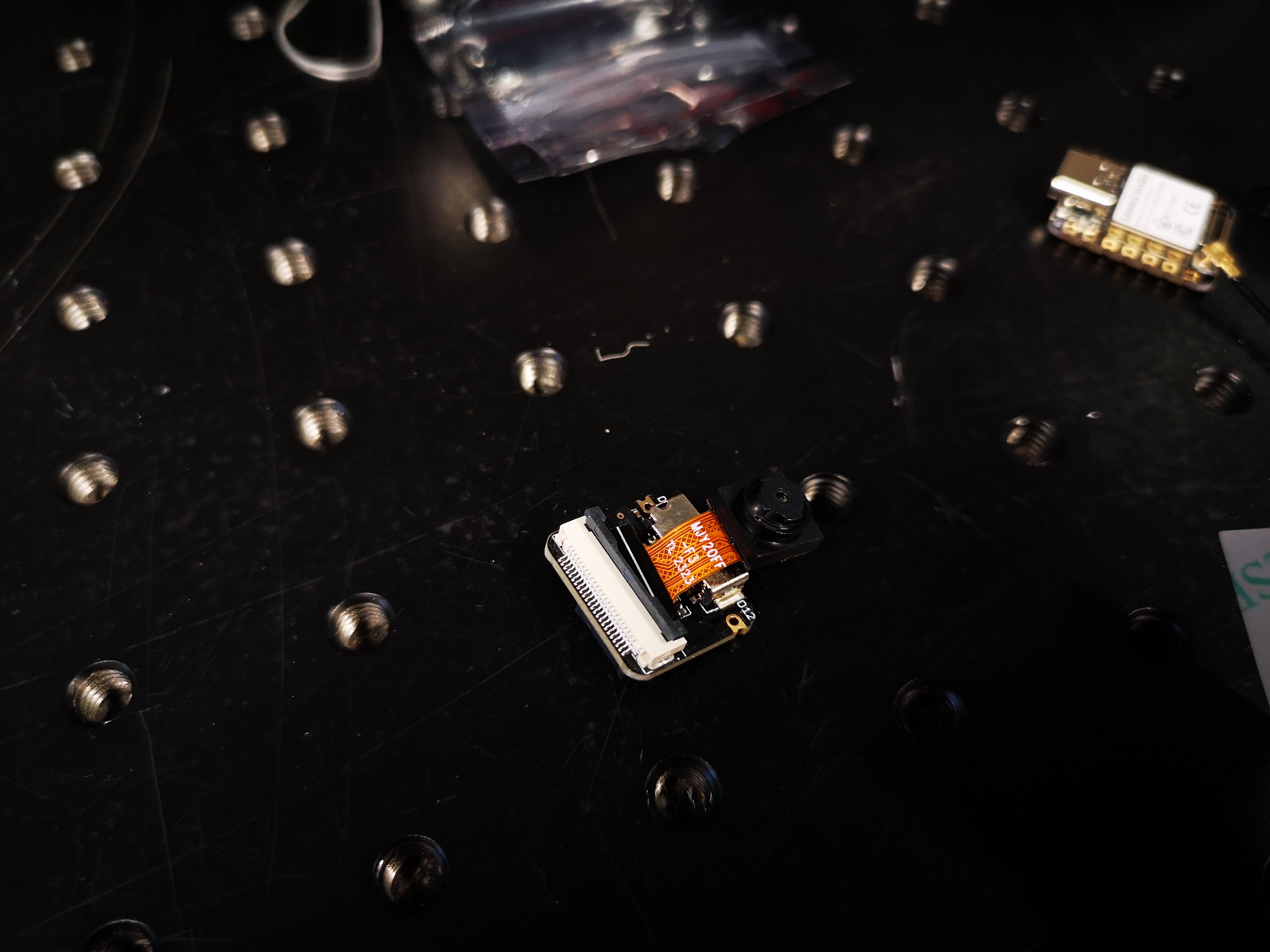
Add the camera holder to the board and fix the camera in place (Hint: If the Camera is not holding properly, you could use blutek or double sided sticky tape to fix it temporally. WARNING: be careful with the flex-pcb (copper one) since this easily breaks if not handled with care); Make sure the flatband cable is oriented correctly and the camera sensor (round, shingy side) points to the SD card slot as indicated in the image below. Make sure you have a good mechanical connection between the flat-band cable and the snap-bar-like mechanism of the ESP-CAM board. Carefuly pull the connection and see if it won't go off.
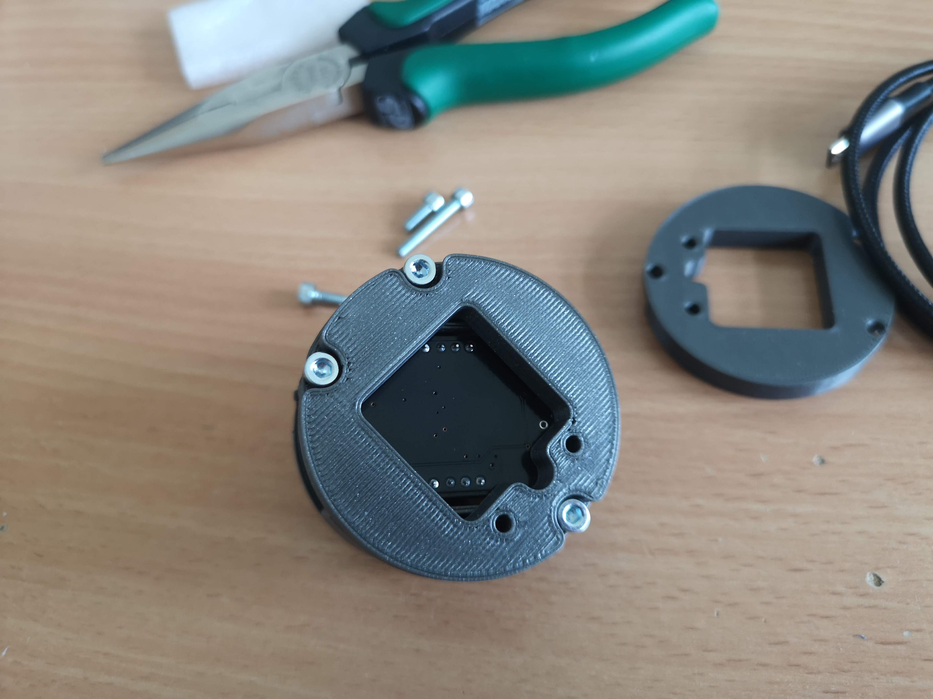
Add the ESP32 board to the base so that the camera tube fits into the hole in the base
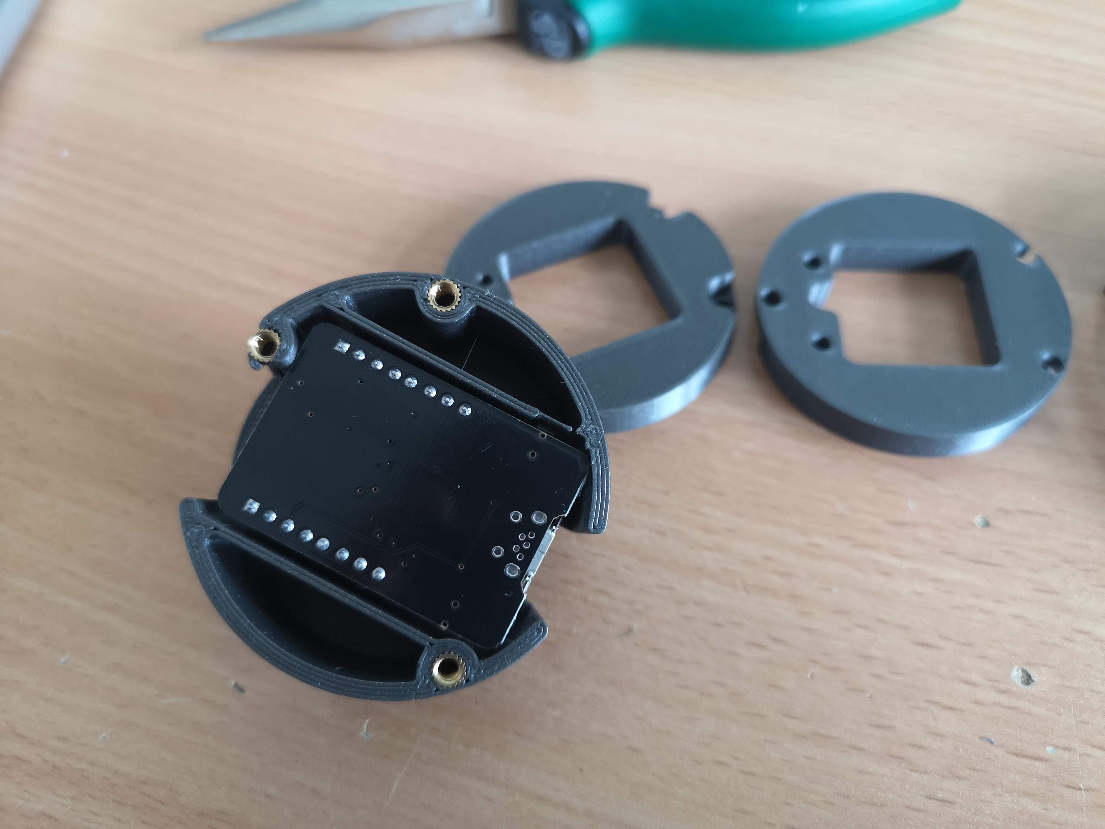
Close the base with the lid from below using M3x12mm screws (not using too long screws); HINT: Make sure the lid(s) are oriented such that the screw holes are pointing outwards as indicated in the image below:
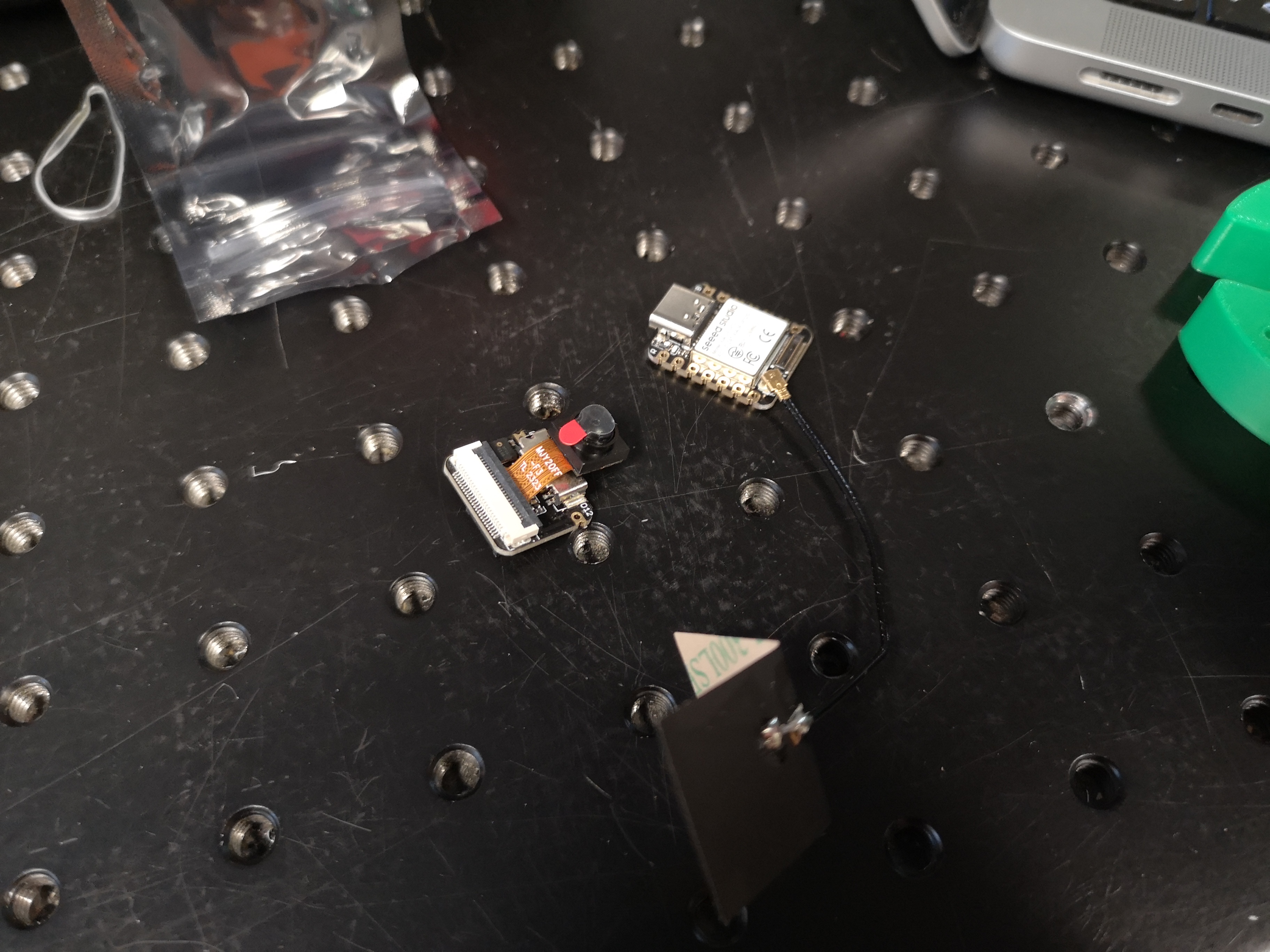
Variation: Seeed Studio Xiao Camera
Instead of the ESP32-CAM, we can also use the newer ESP32-S3-based camera from Seeed Studio. It's a lot smaller and more powerful. But beware: It gets hot! Plastic may start melting. For this board, choose the XIAO firmware in the flashing process.
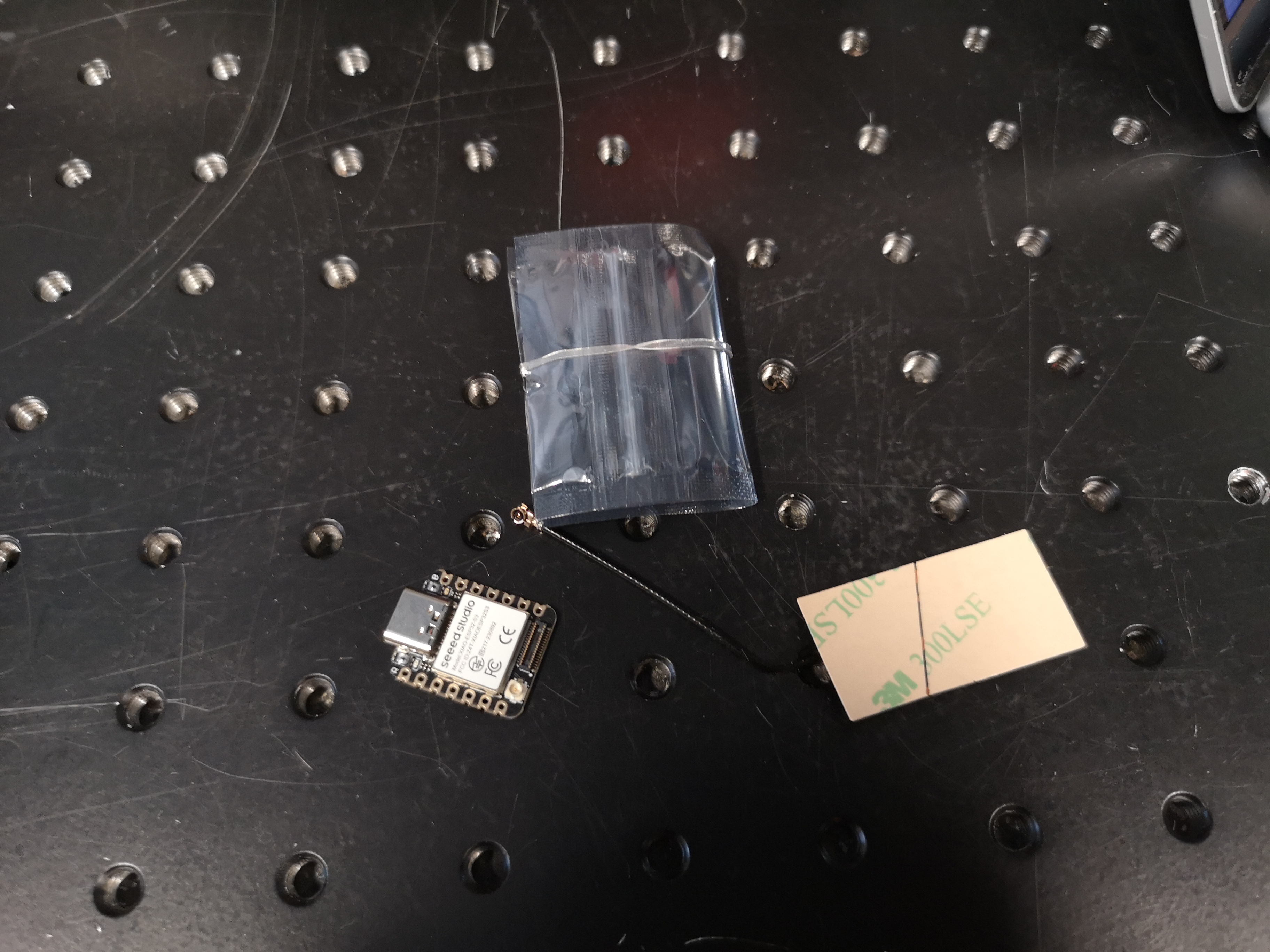
These are the parts needed; You can retrieve them from here:
https://github.com/Matchboxscope/Matchboxscope/releases/tag/XIAOSeeedStudioV1
Steps to reproduce
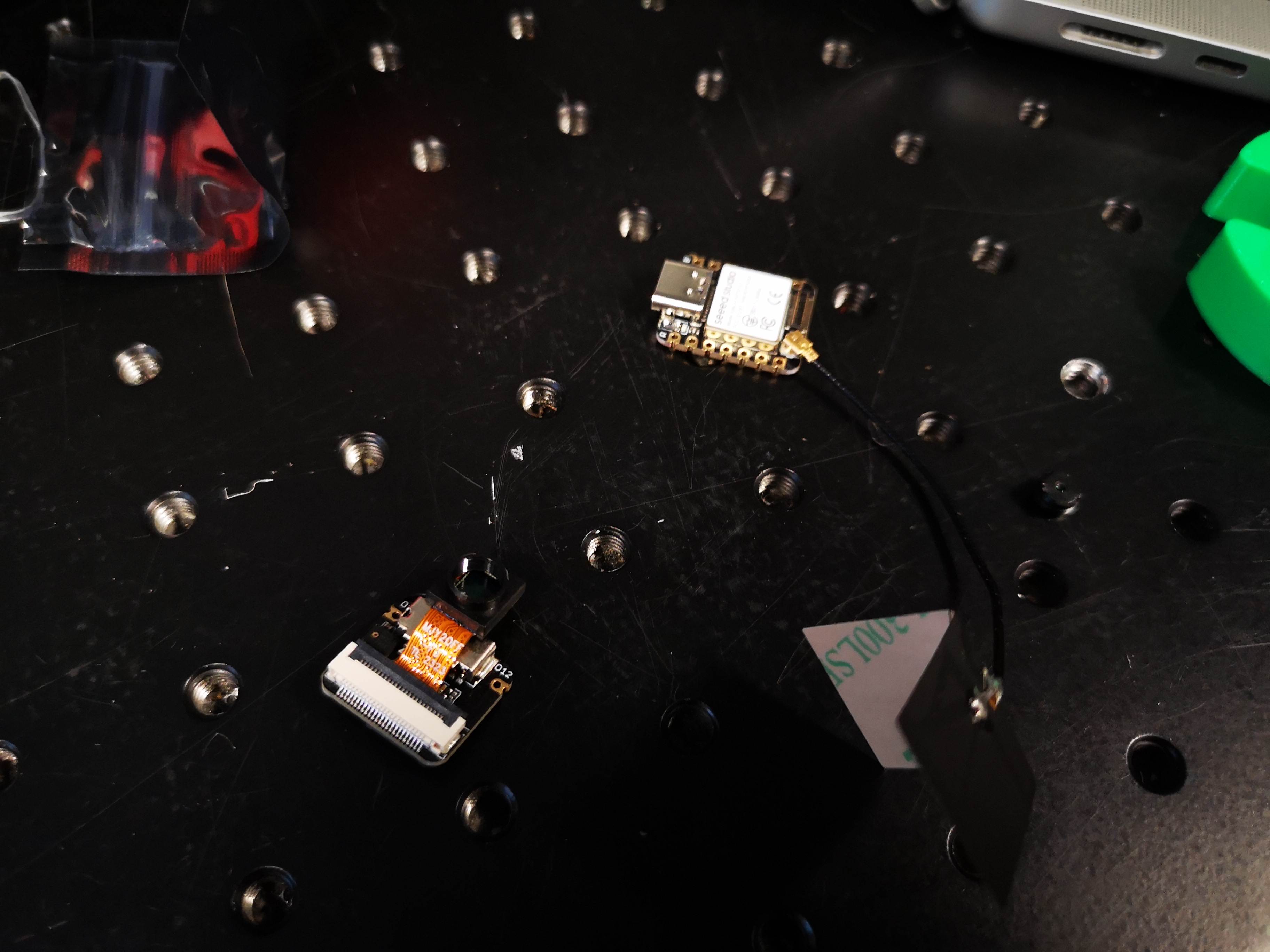
- Prepare the Case by adding the threaded inserts using the hot iron
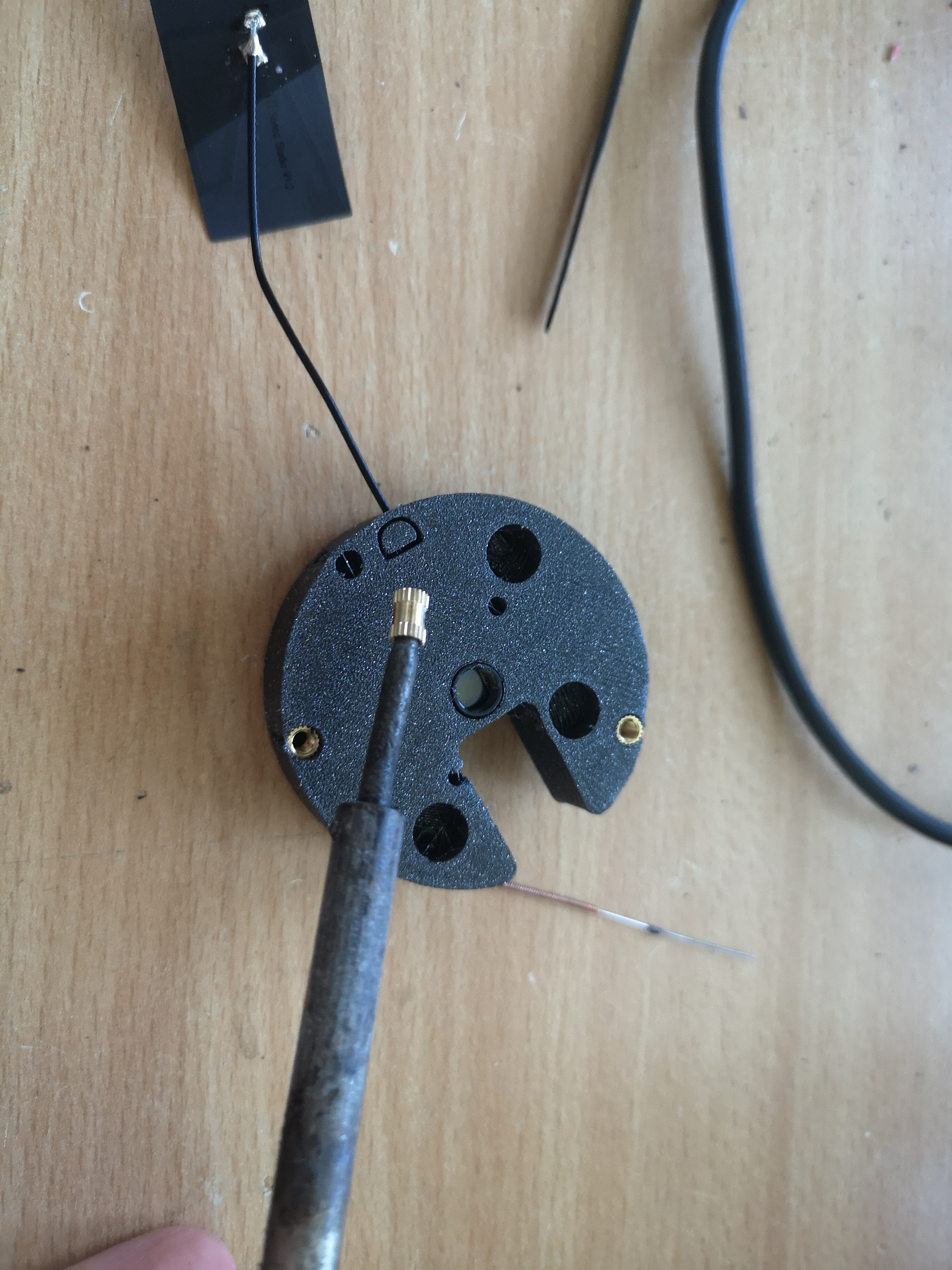
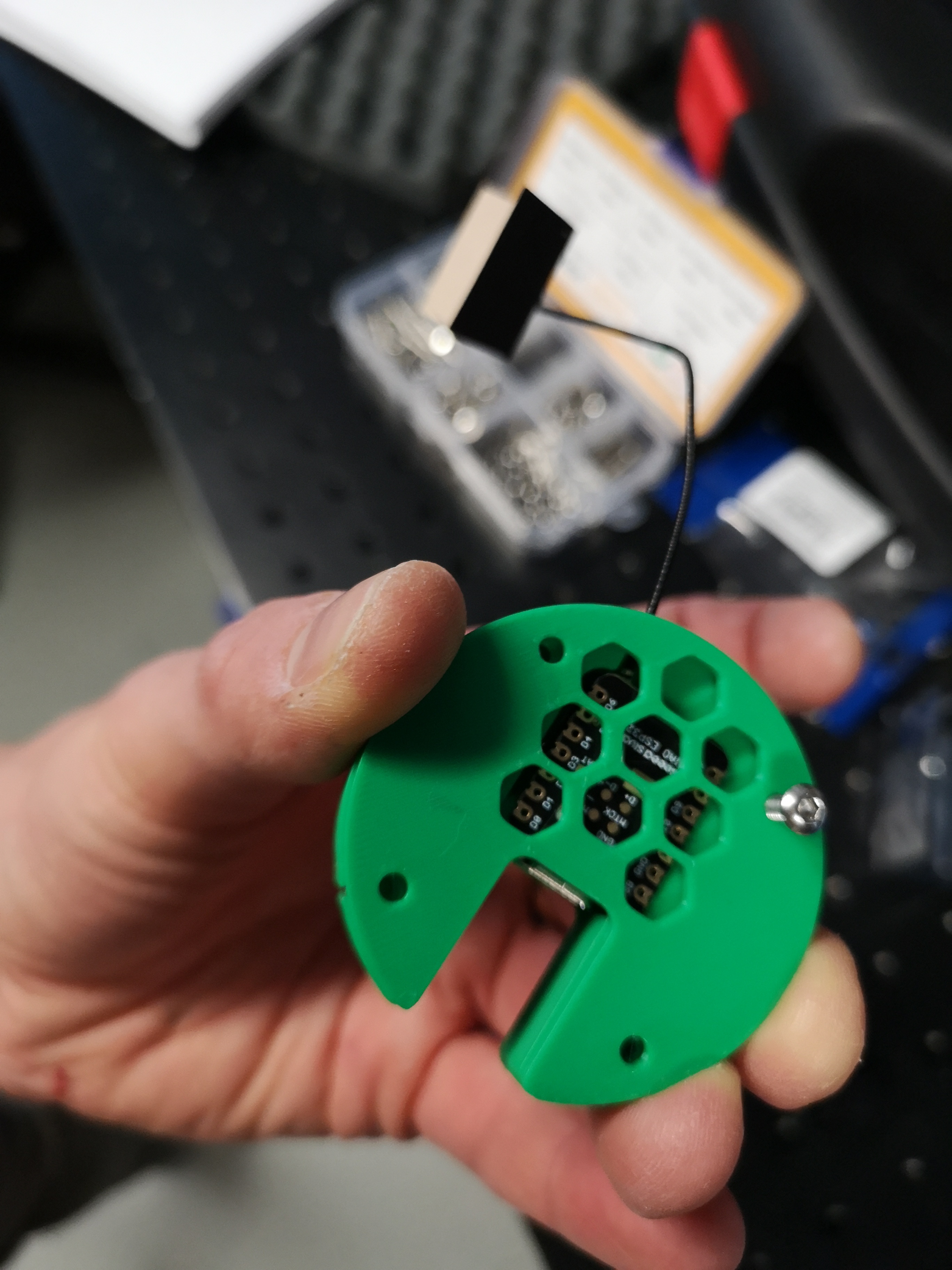
- Add the Xiao to the base after removing the lens from the camera. Make sure the camera is parallel to the surface; An SD card (dummy) may help
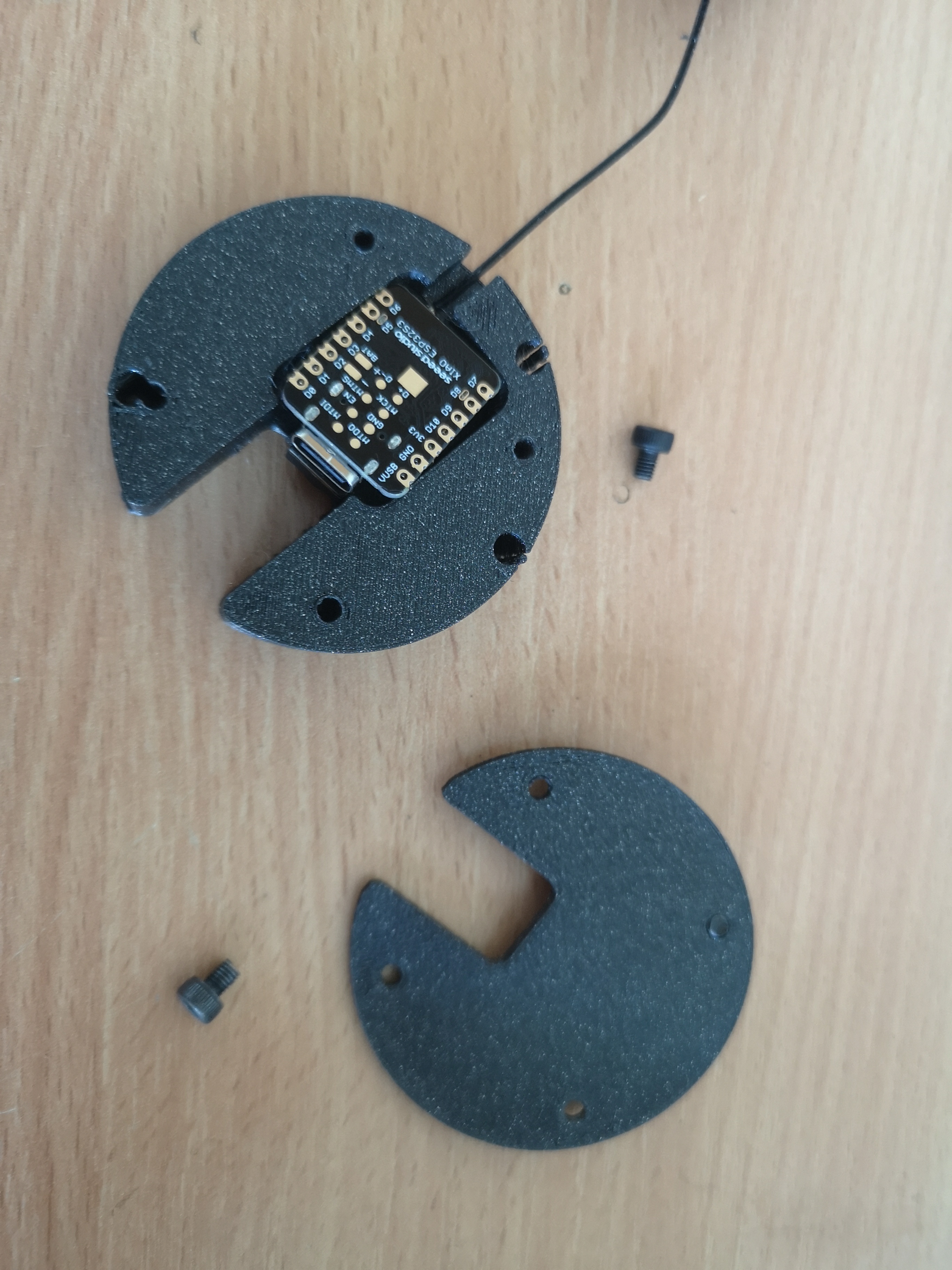
- Add the lid and short M3 screws to close it. Done.
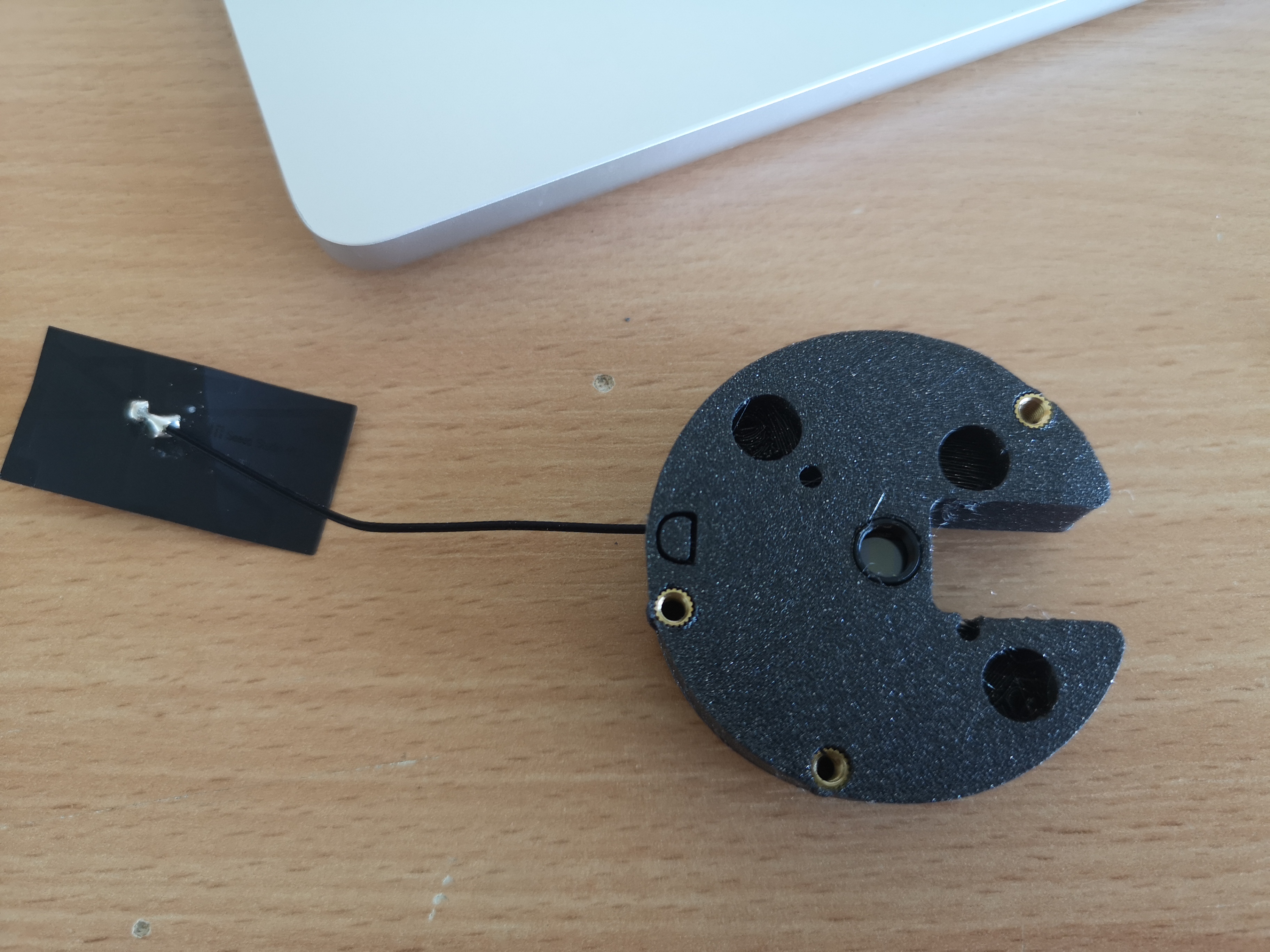
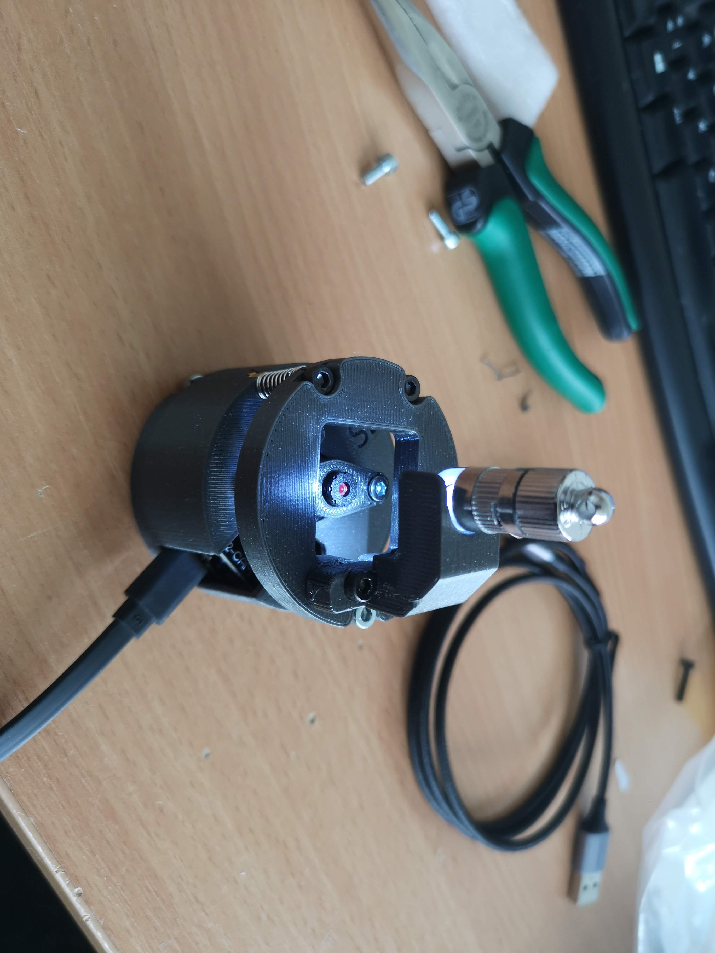
- Add the springs to the screws and mount the sample plate using M3x24mm screws; Add the lamp holder using the M3x12 screw.
HINT: This is a bit tricky. Start with one screw+spring combination, fix it and continue with all others. In motion:
- Add the lamp - done!
Done
Operation
Find the focus
Turn on the light. Take a piece of paper and first try if you can sense any contrast variation in the camera stream. Try to turn the 3 spring-loaded screws such that the stage z-position becomes coincident with the position of best contrast with the piece of paper. Try to keep the stage parallel to the base.
Software
Capturing imates
If you start the stream and hit the Capture button, the image gets stored on the internal SD card (if inserted). For this, please flash it using the official SD card formatting tool: https://www.sdcard.org/downloads/formatter/
Browser-based operation
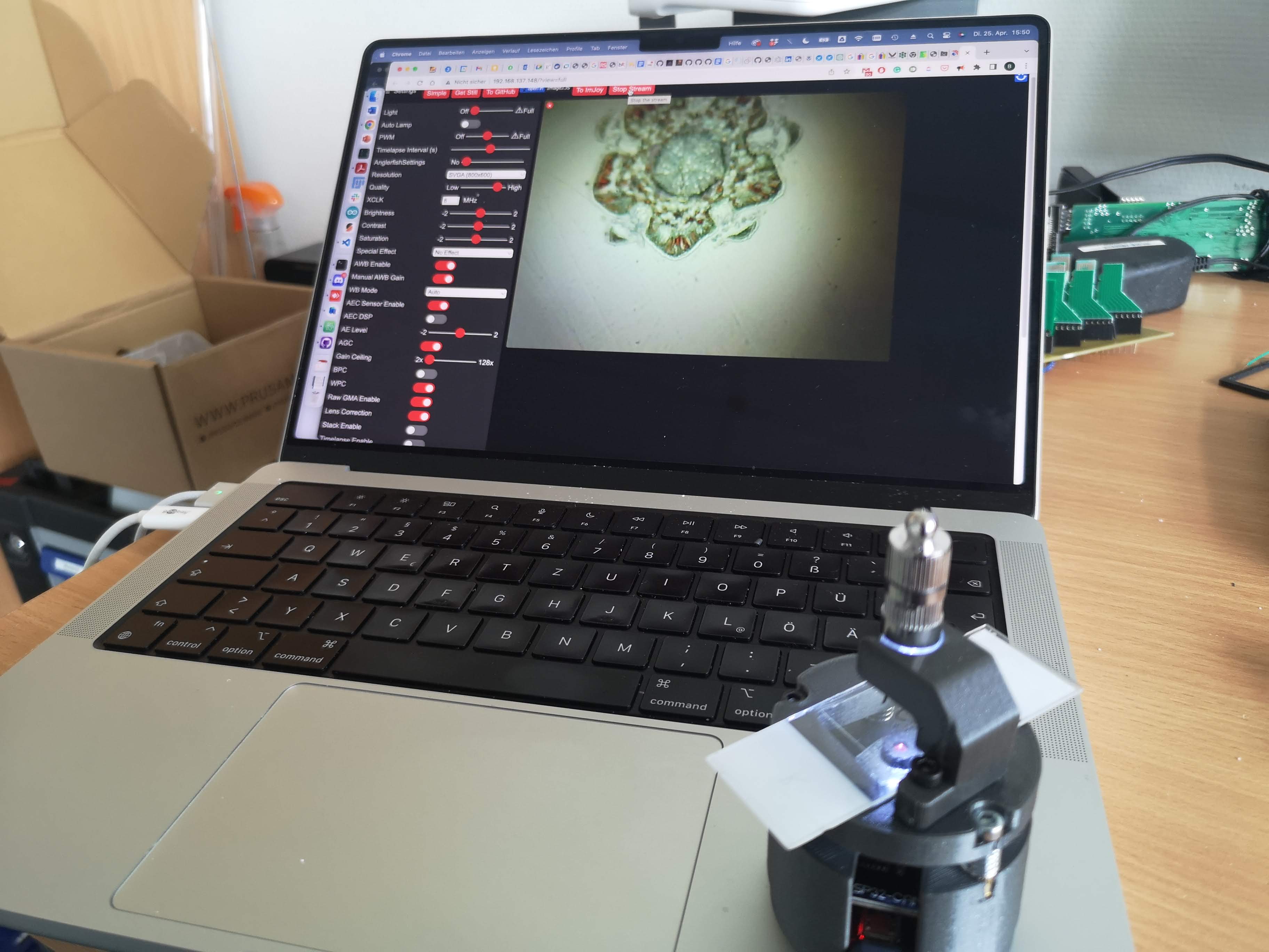
You can connect to the ESP32 using a wifi-enabled device that runs a browser (mostly tested with Chrome). Find the device's IP address (e.g. by observing the Serial output) and enter this address into the browser's address bar. The UI comes in simple and advanced mode. Open advanced. Play around with the settings. You can tweak it to be fully manual, however, the image data will always be JPEG compressed (sorry).
ImJoy/ImageJ.js
When the stream is running, you can send an image to the in-built ImJoy/ImageJ.js plugin. There you can do all kinds of image processing tasks as you know from Fiji. Note This will only work if the stream is running. Once you hit the send to ImJoy button, the stream will pause. For another image, you have to restart the stream first.
GitHub upload
Similar to the ImageJ.js functionality, the ESP32 can trigger a git push of the latest frame from the camera stream to a gallery repository available here https://github.com/matchboxscope/Matchboxscope-gallery. The image resolution will be altered to a much smaller value, (320x240 pixels^2) so that the upload won't timeout (unknown reason??). This change in resolution leads to an over exposed image with previously adjusted settings.
The uploaded images get compiled into a JS-based gallery daily, available here: https://matchboxscope.github.io/gallery/matchboxgallery
Autonomous operation
If a FAT formatted SD micro card is inserted, you can record timelapse image series with the previously entered settings. Two modes are available. One, where the network operatibility is still available, the other when it'S in deep-sleep mode (e.g. under water).
HINT: Please format the SD card using the official SD card formatter: https://www.sdcard.org/downloads/formatter/
Non-deepsleep timelapse
Adjust the value in the timelapse slider to something between 0-600s. The image gets stored on the SD card.
Deep-sleep timelapse
To enter this setting, you have to move the slider for Anglerfishmode all the way to the very right. A link appears that will activate the deep-sleep time lapse feature. It will use the previously set period in the timelapse slider. All settings that have been entered through the GUI will be used for imaging + an exposure series of 1,5,10,50,100,500ms will be acquired. Images get stored on the SD card. To exit the "boot loop", you simply remove the SD card and it will turn back to normal mode,where it tries to connect to the previously set wifi connection.

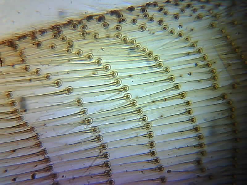
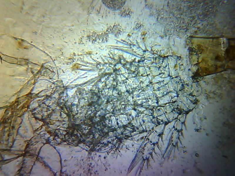
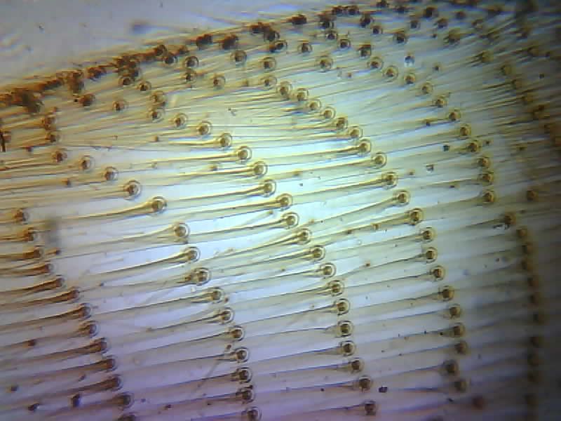
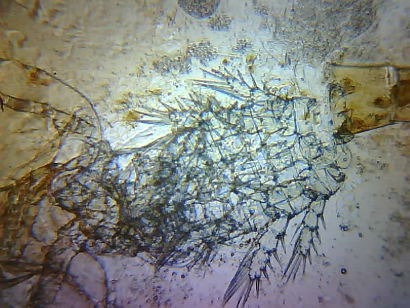
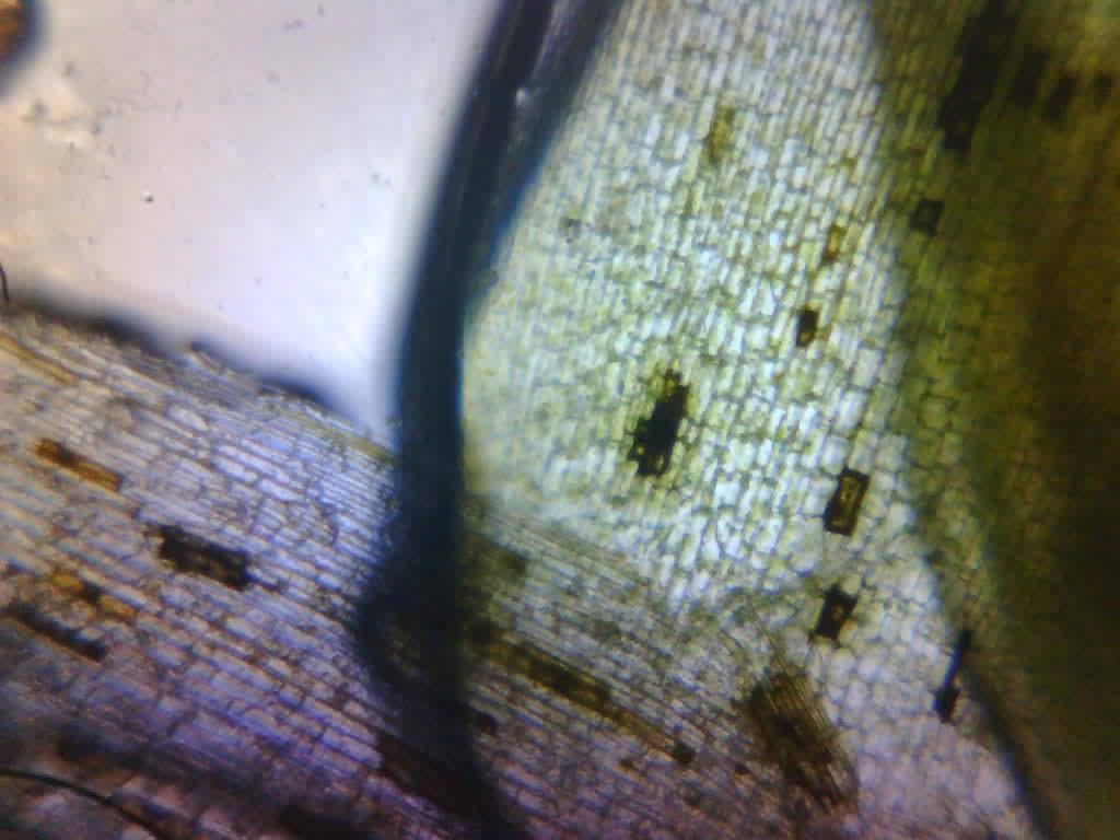
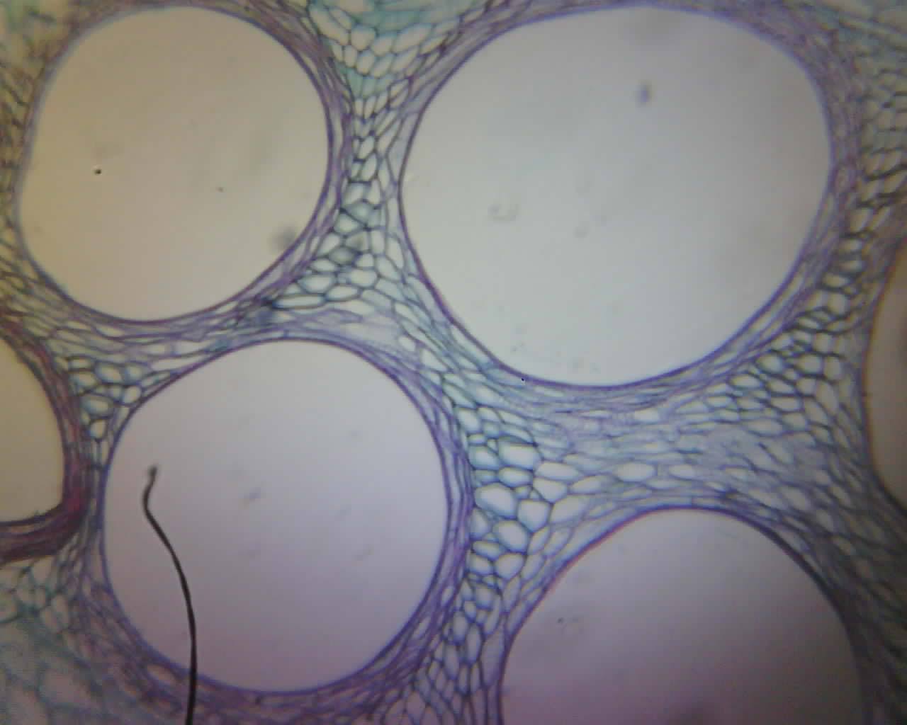
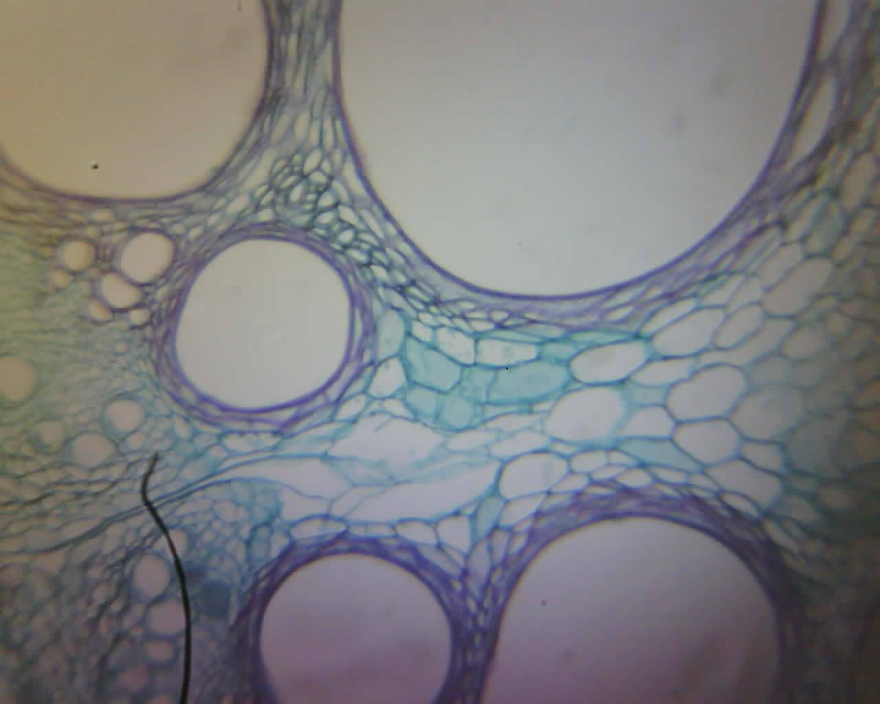
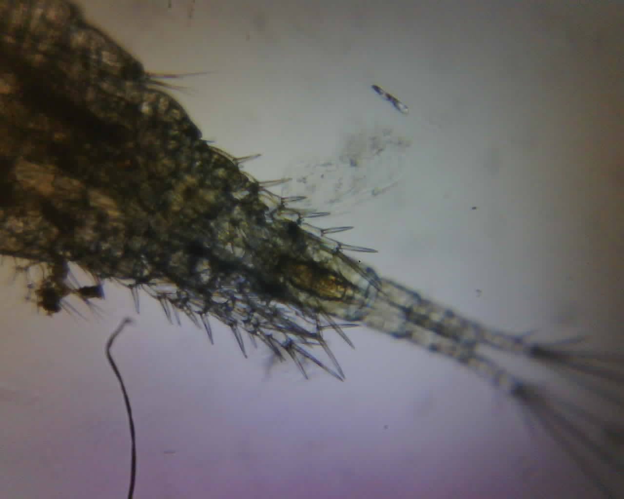
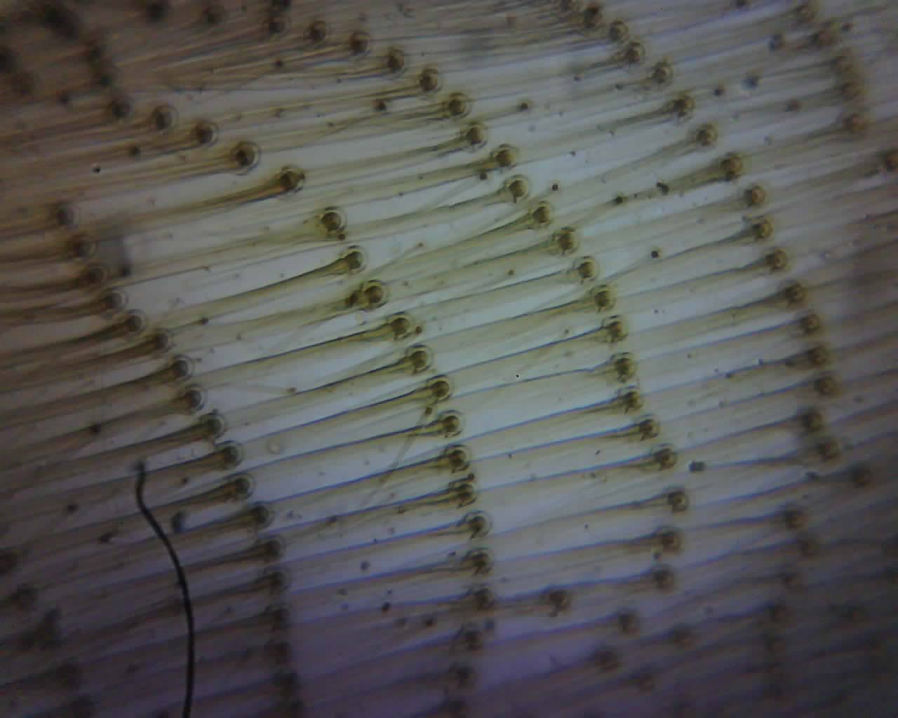
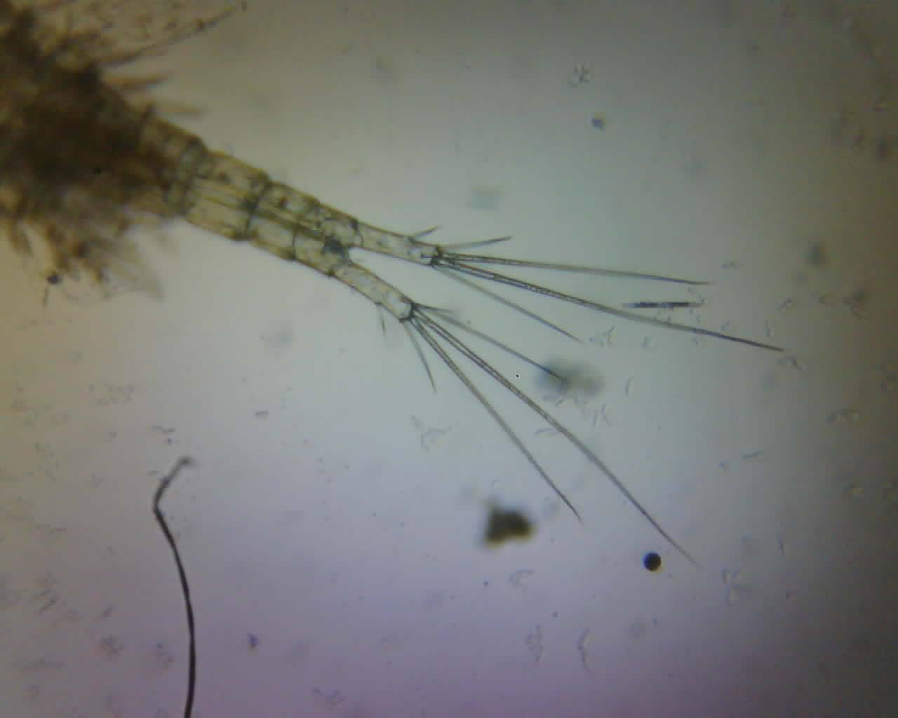
Imaging Results
HeLa cells in an incubator while they are dying (sad but true)

Showcase