Fluidiscope
Microscopy is a key tool in many scientific fields, including medical research, environmental monitoring, and materials science. However, current microscopy techniques often have limitations in terms of accessibility, flexibility, and high-throughput sample monitoring. To address these challenges, we developed an ESP32-based microscope with a peristaltic pump module for continuous or controlled flow. It can be used for microplastics, yeast, plankton... find it out! :)
Traditional microscopy techniques often require specialized expertise, expensive equipment, and limited flexibility. Furthermore, high-throughput sample monitoring can be challenging using traditional microscopy methods. To overcome these limitations, we designed an ESP32-based microscope with a peristaltic pump module* to enable continuous or controlled flow. The microscope is equipped with a decent camera module for high-resolution imaging and real-time video capture. The peristaltic pump module is added to the microscope assembly using a tube that adapts to the pump. A second ESP32 is used to control the stepper motor 28byj-48, which drives the pump.
Assembly
We will give you a step-by-step guide how to assemble the fluidics part. The microscope (i.e. matchboxscope remains the same. If anything fails or doesn't match as expected (most likely), please file an issue immediately. We will be there for you. Illumination: Since we wanted to try different illumination scenarios, we added the IKEA USB Lamp to the assembly. It'S powered by the ESP32 USB.
The Teaser
 { width="400" height="300" style="display: block; margin: 0 auto" }
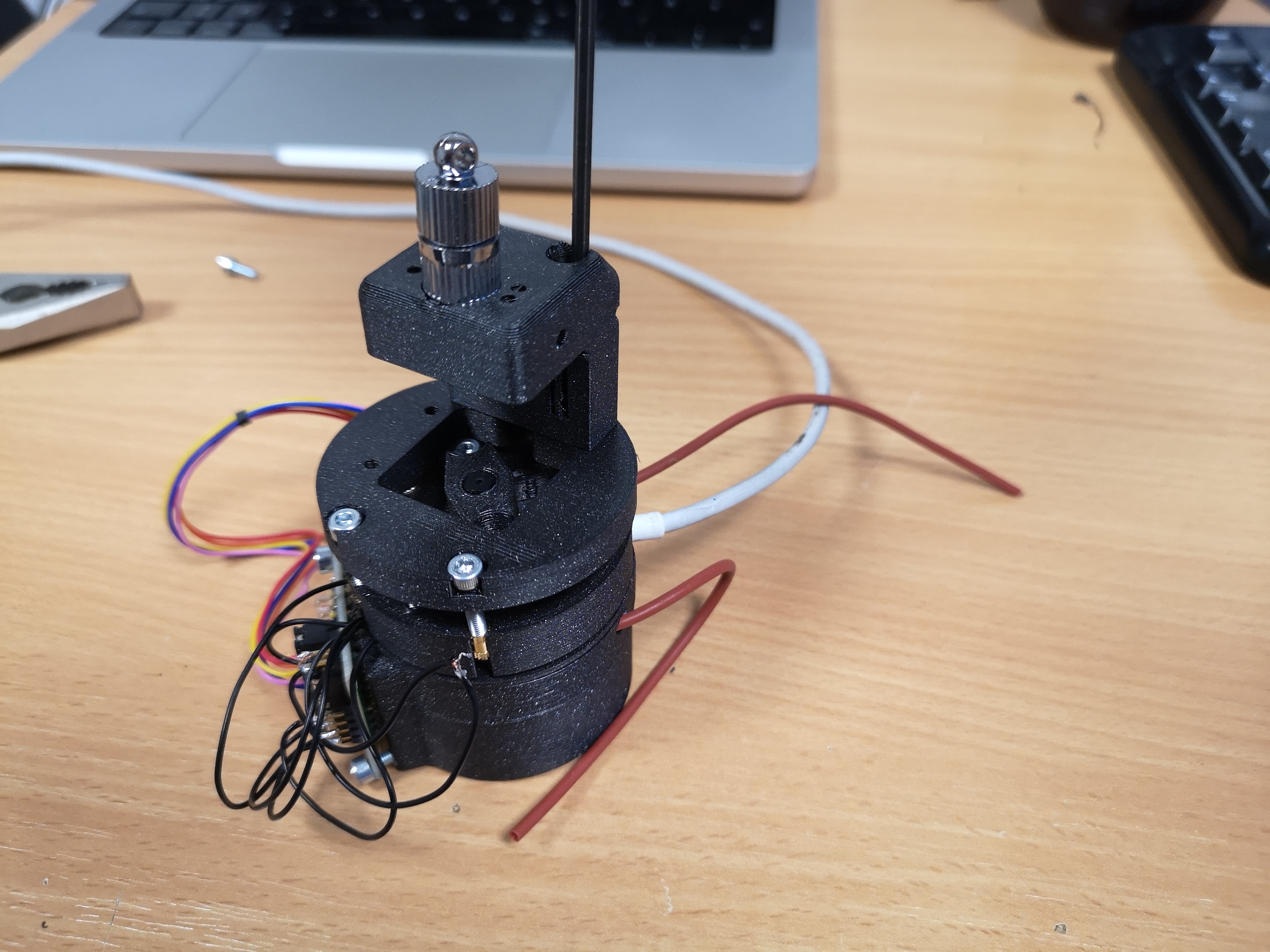
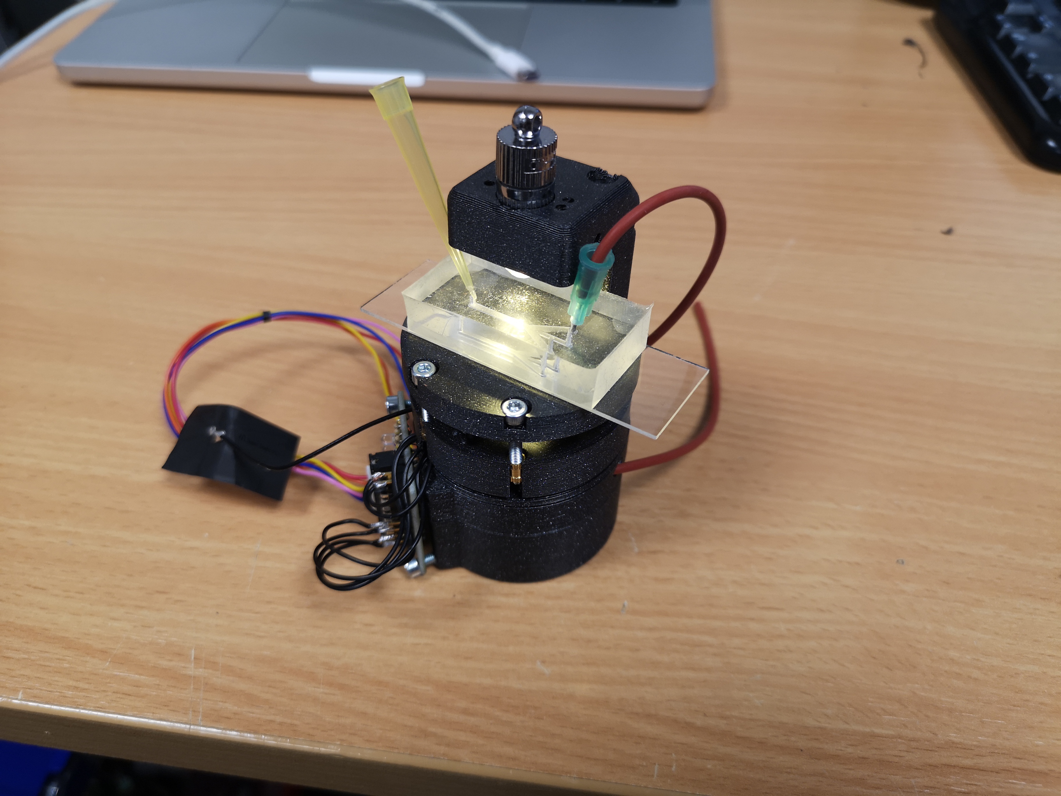
The Rendering
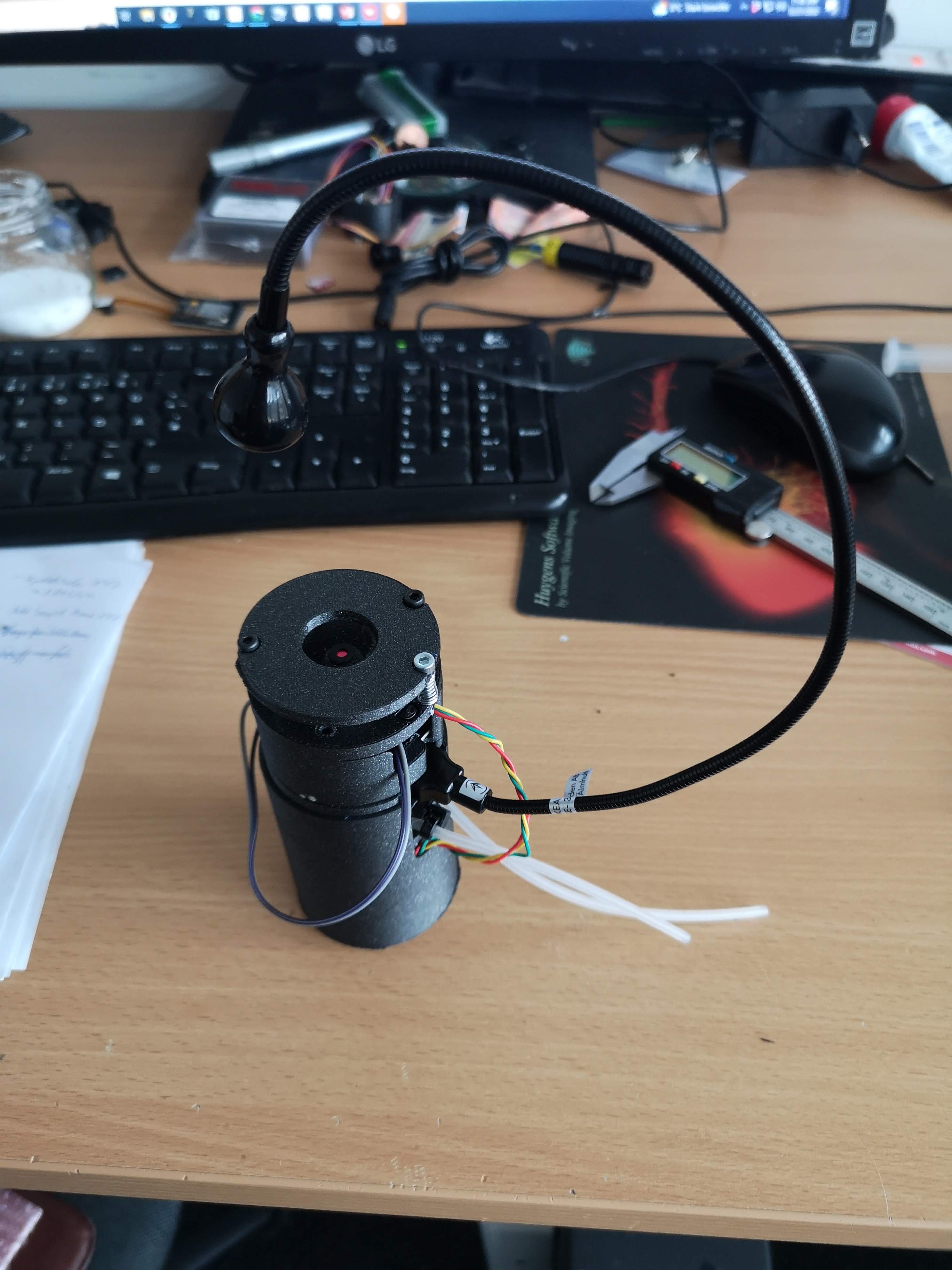
In Reality
Components
This you will need for your device in order to work:
Bill of material
(only for the perestaltic pump)
| Part | Purpose | Source | Price |
|---|---|---|---|
| ESP32 D1 mini | Controls the pump, receives PWM signal 0..3V3 (fwd/bwd/0) | AZ | 10 € |
| Ball bearing 8x3mm | Push the tube | 0.5€ | |
| 3D printing material (PLA) | |||
| Ikea USB lamp | Variable Illumination | ikea | 5€ |
| 28byj-48 + ULN2003 | Rotating Stepper Motor | Amazon | 5€ |
| 5mm silicone tube | for the perestaltic | ??? | 0.5€ |
3D printing files
All design files can be found in the release from the Matchboxscope Releases (Look for miniplanktoscope).
All 3D-printable files can be found here:
CAD Files
The release files can be found https://github.com/Matchboxscope/Matchboxscope/releases/download/ESPMicroscopeCollectionv2/CAD_PlanktoscopeMini.zip
Assembly Process
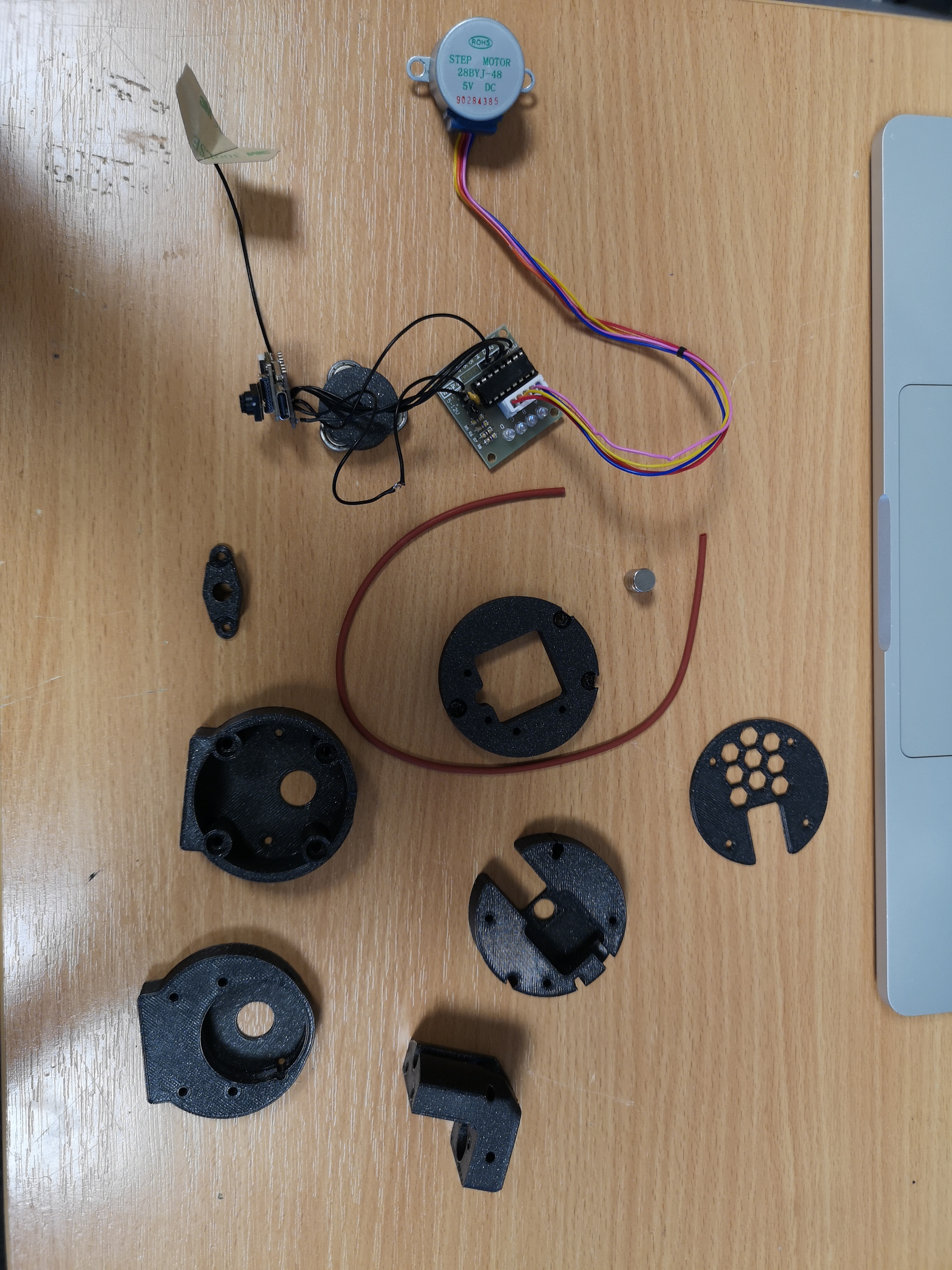
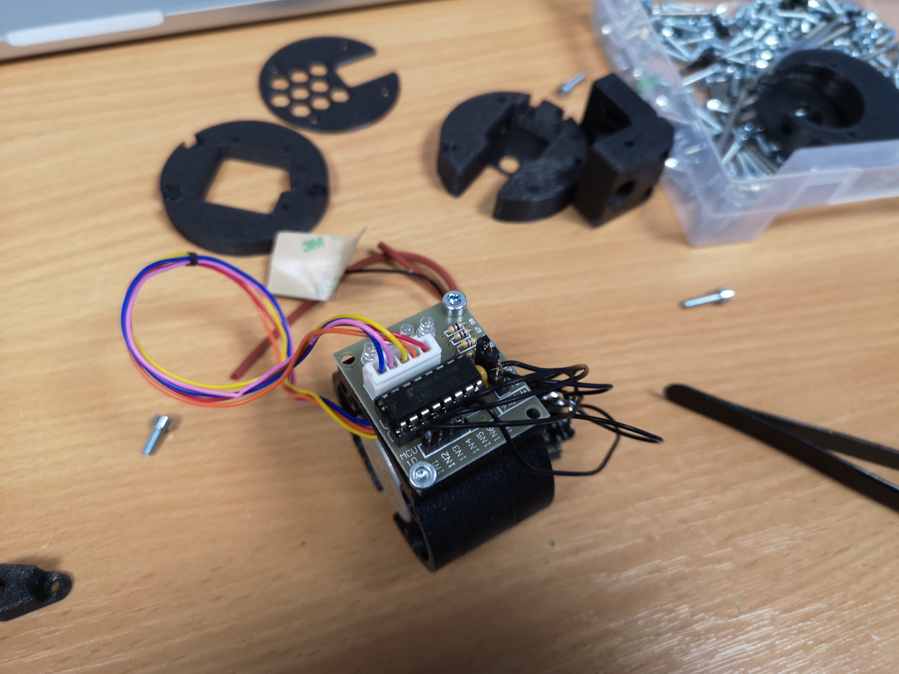
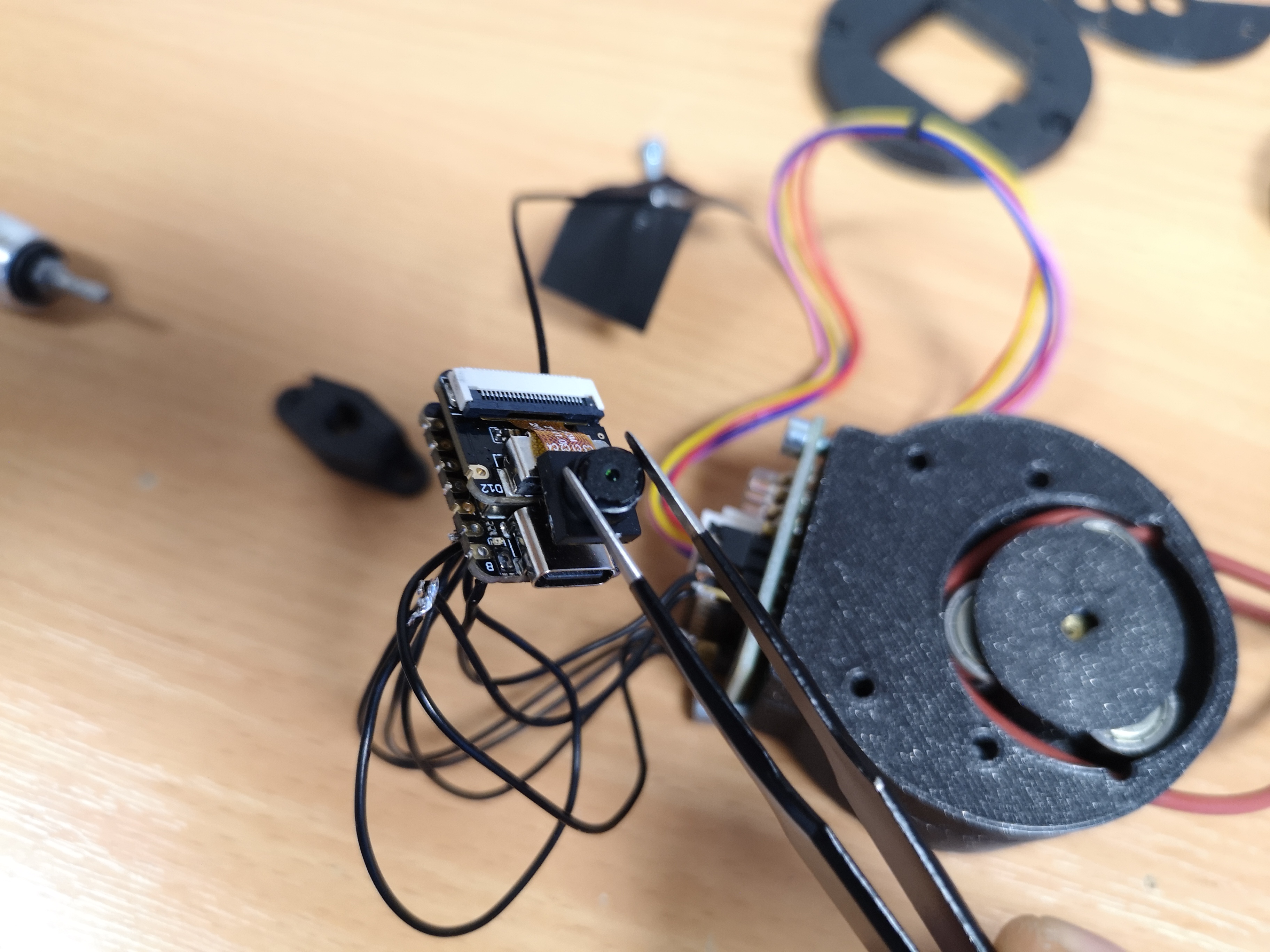
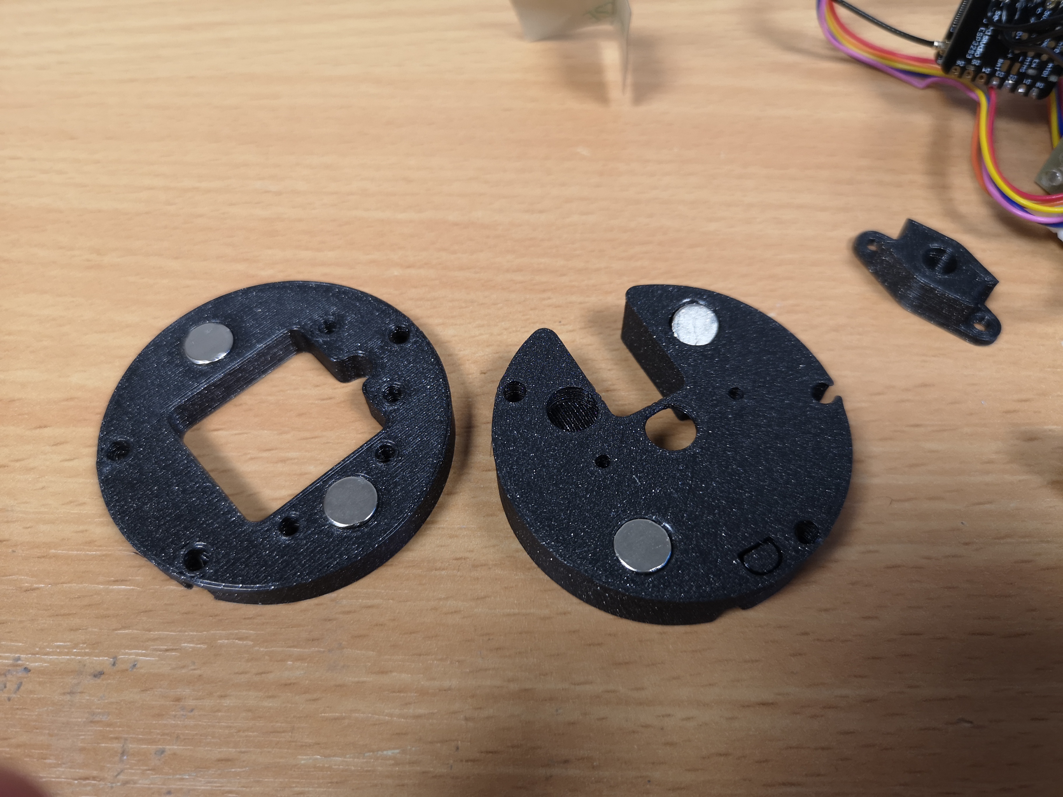
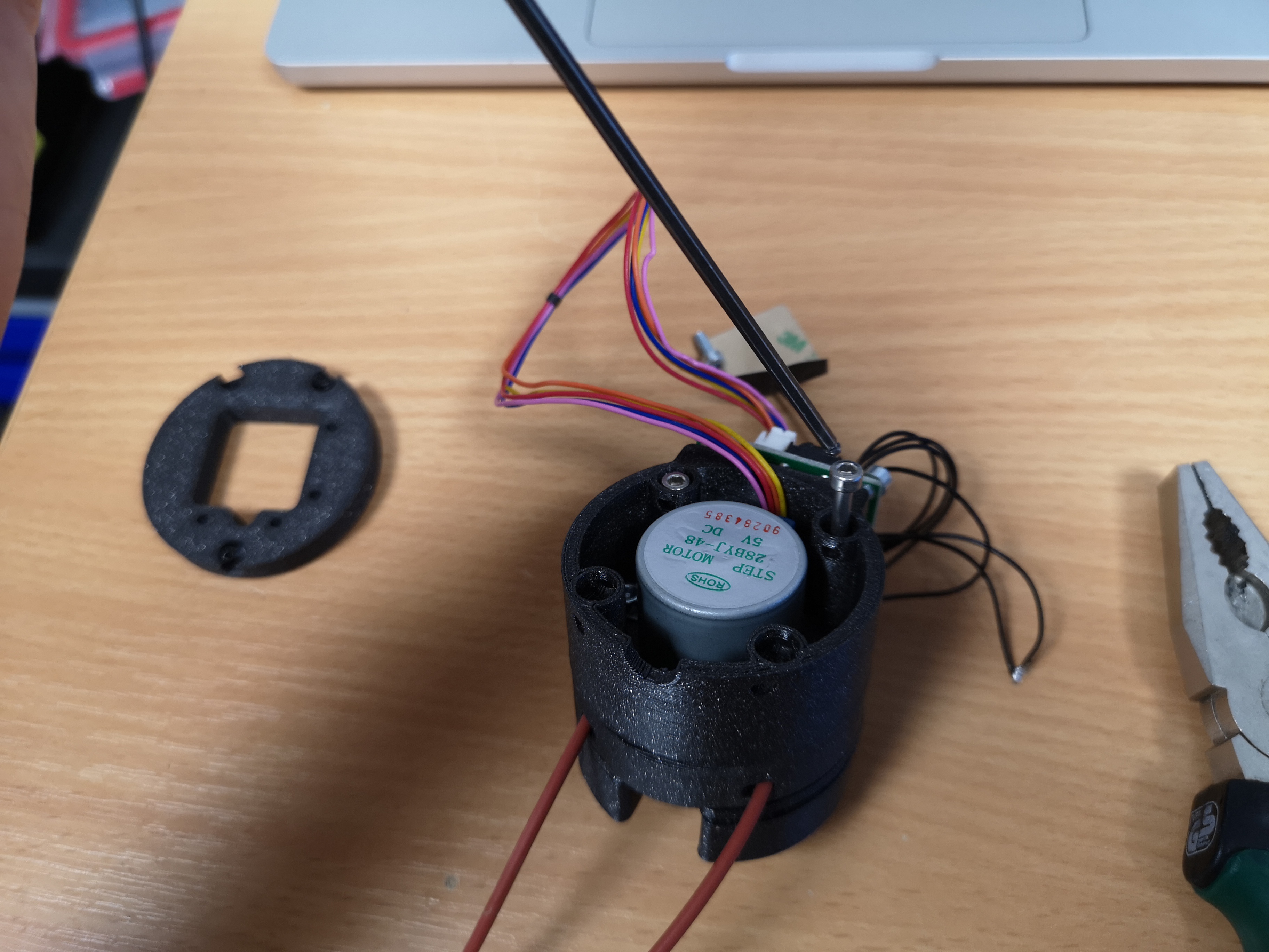
These are the parts you need
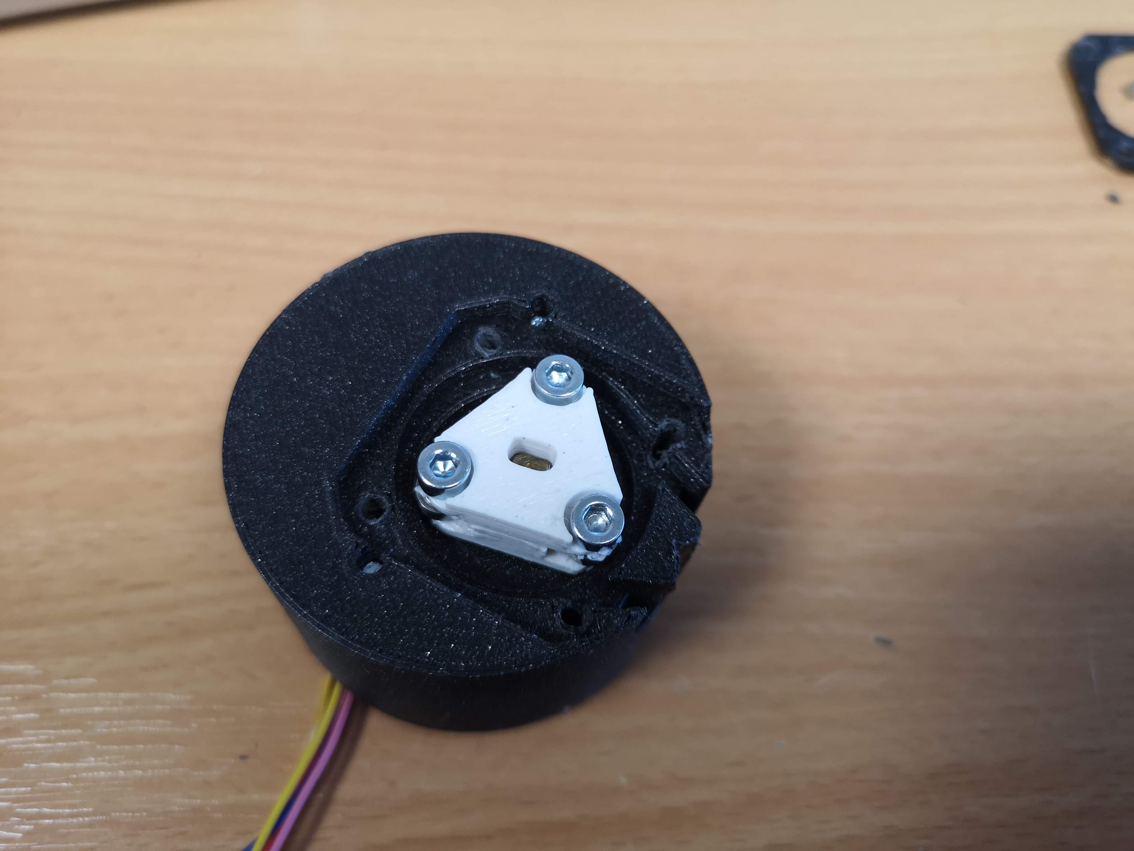
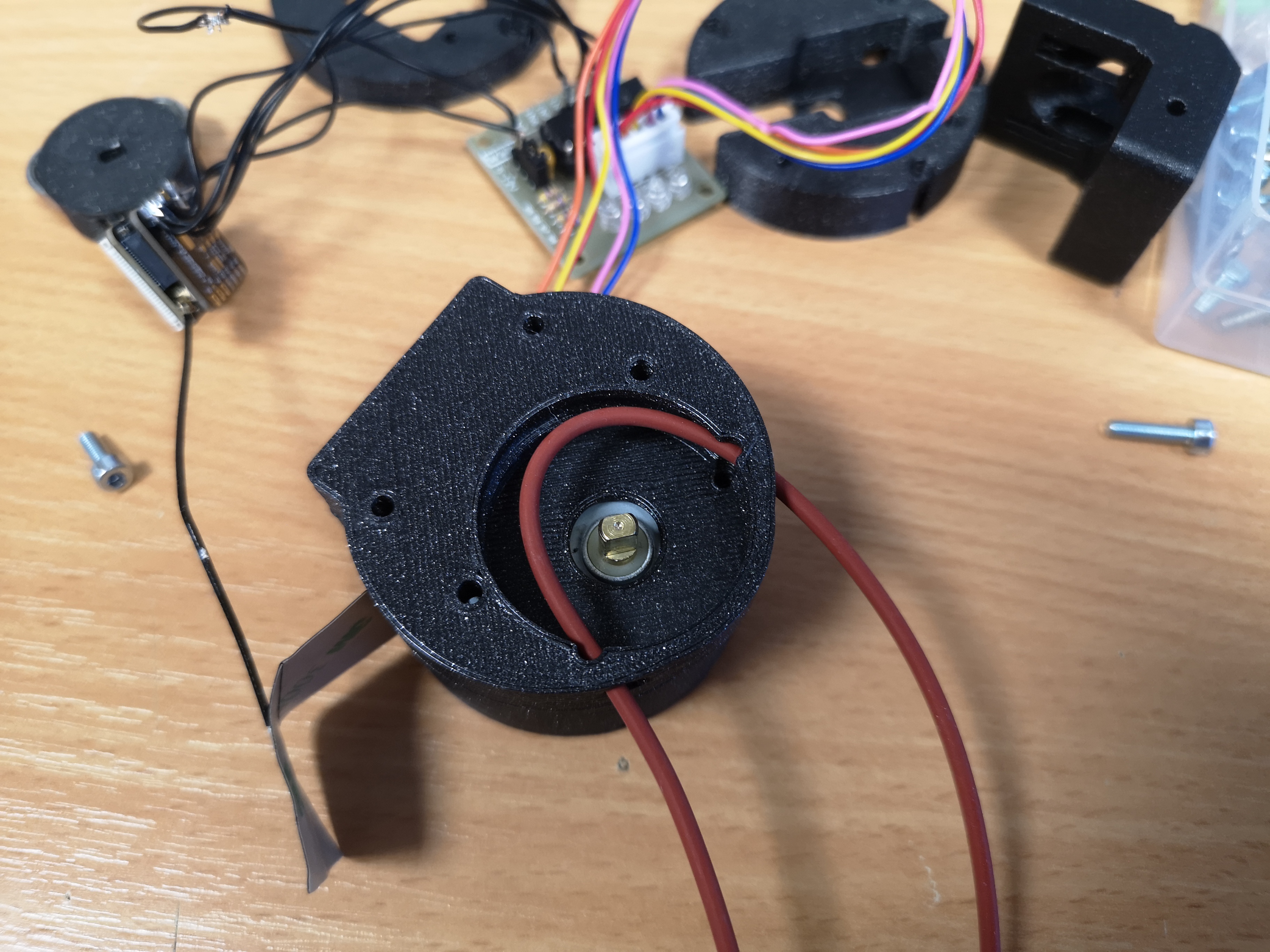
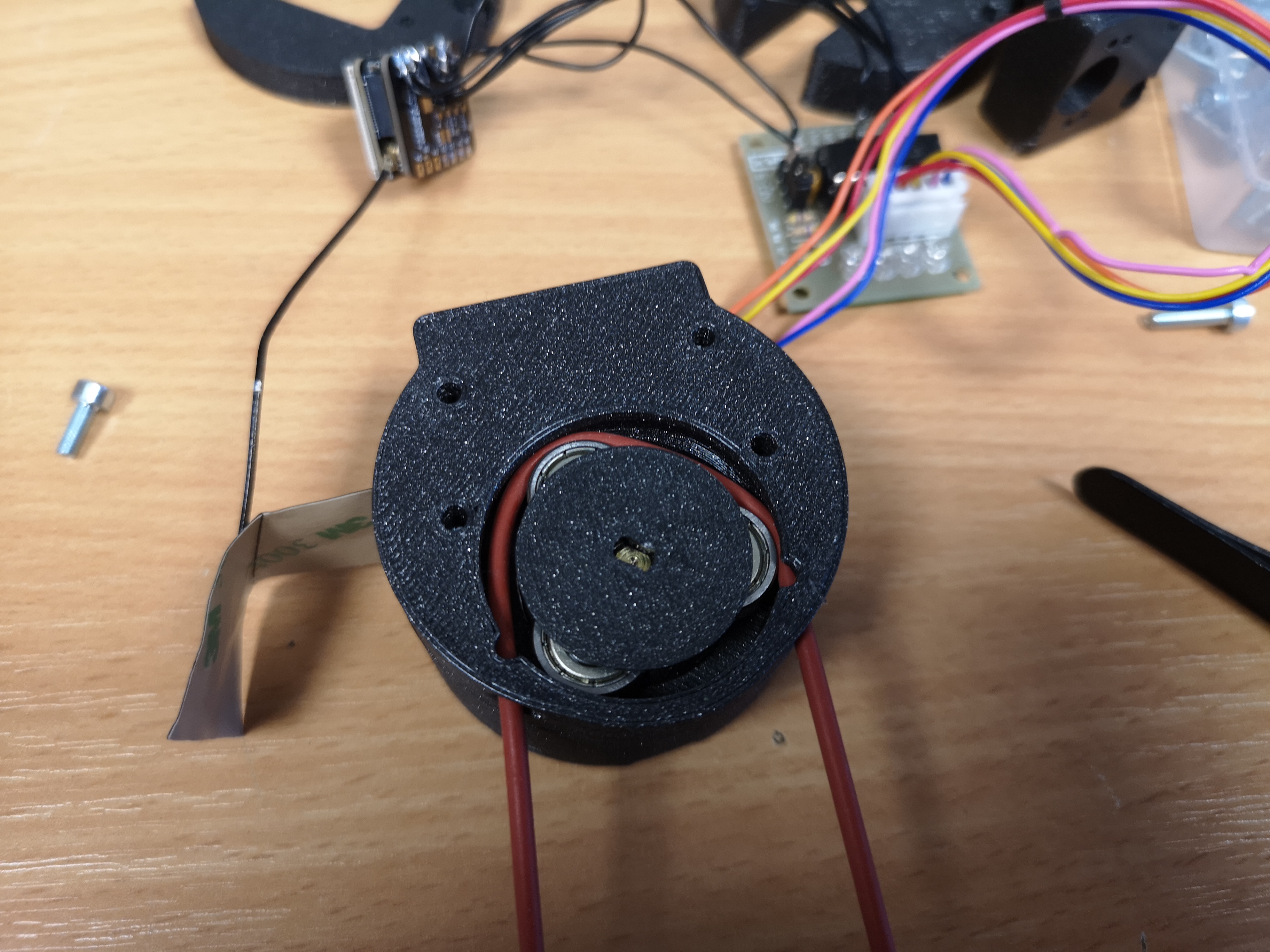
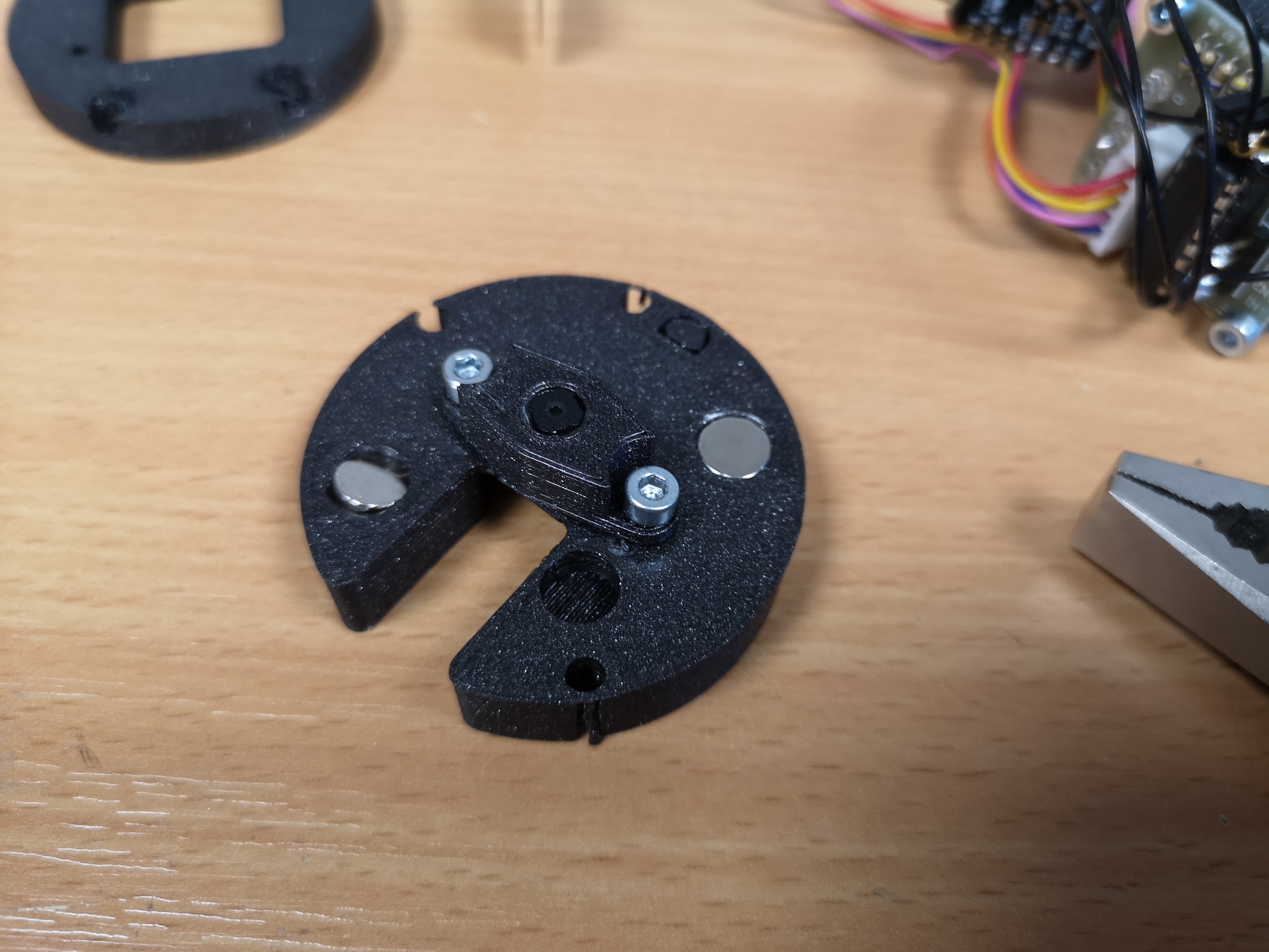
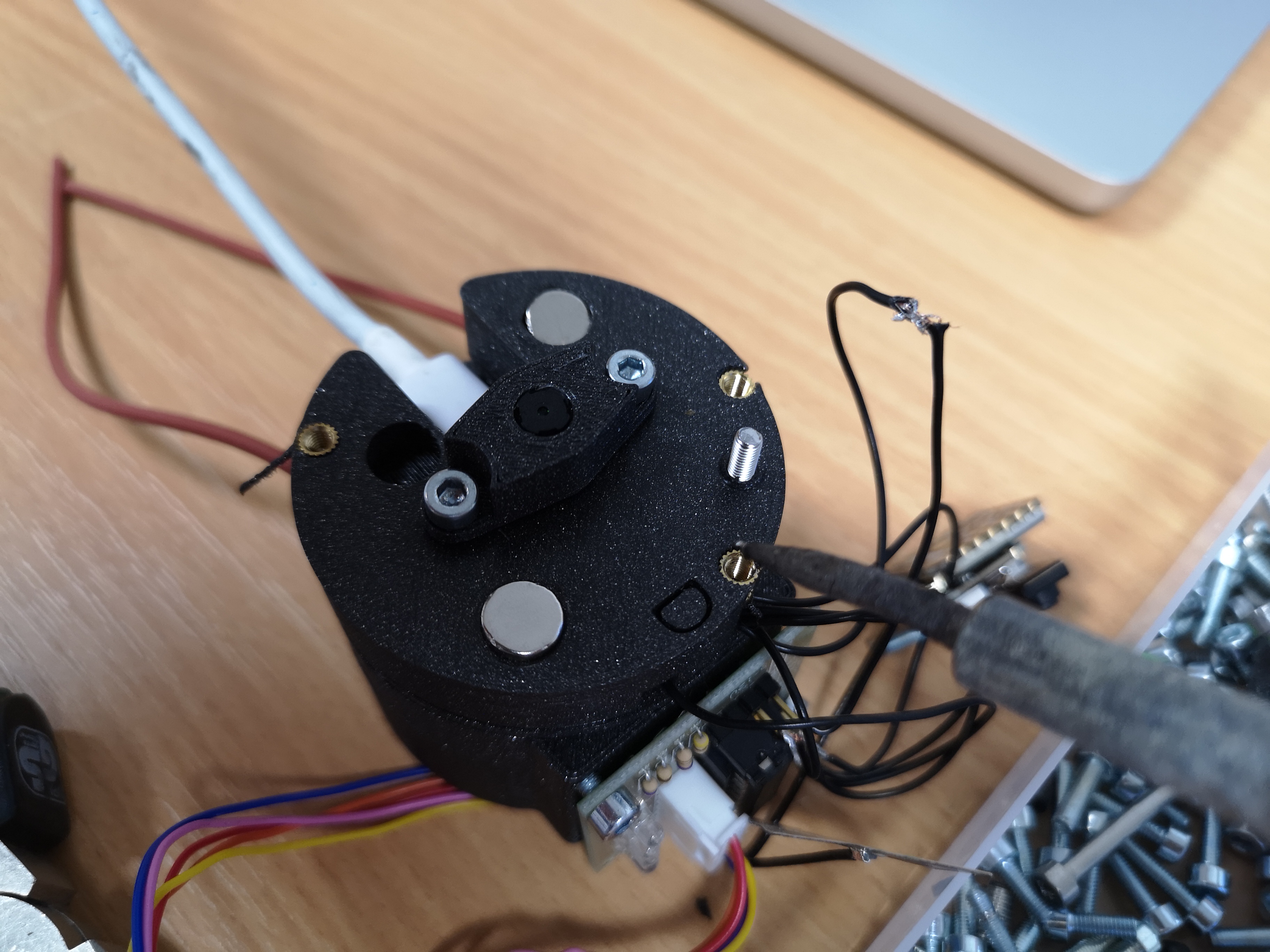
Assemble the perestaltic pump. Add the M3x8 DIN906 to the rotating head and mount the 8x3mm bearings:
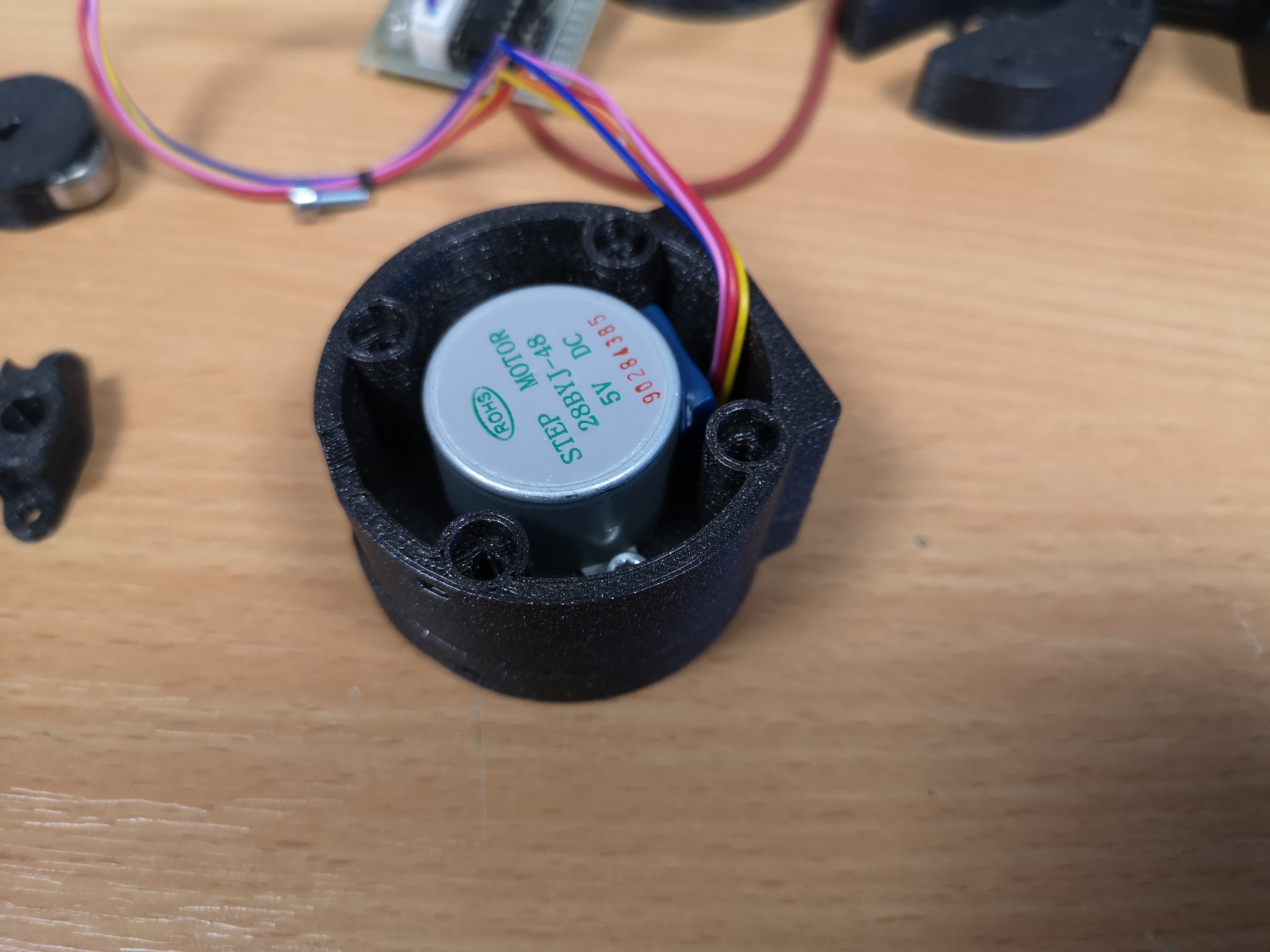
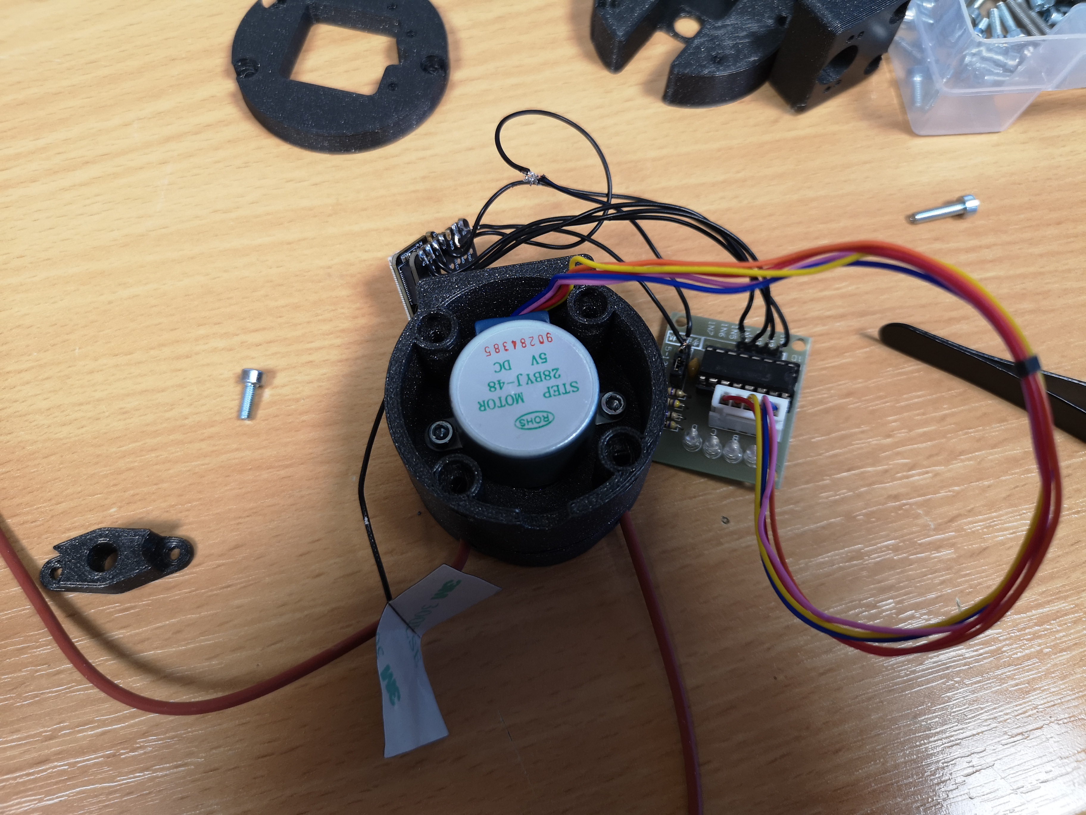
Screw the Stepper motor to the pump-base with M3x12mm screws
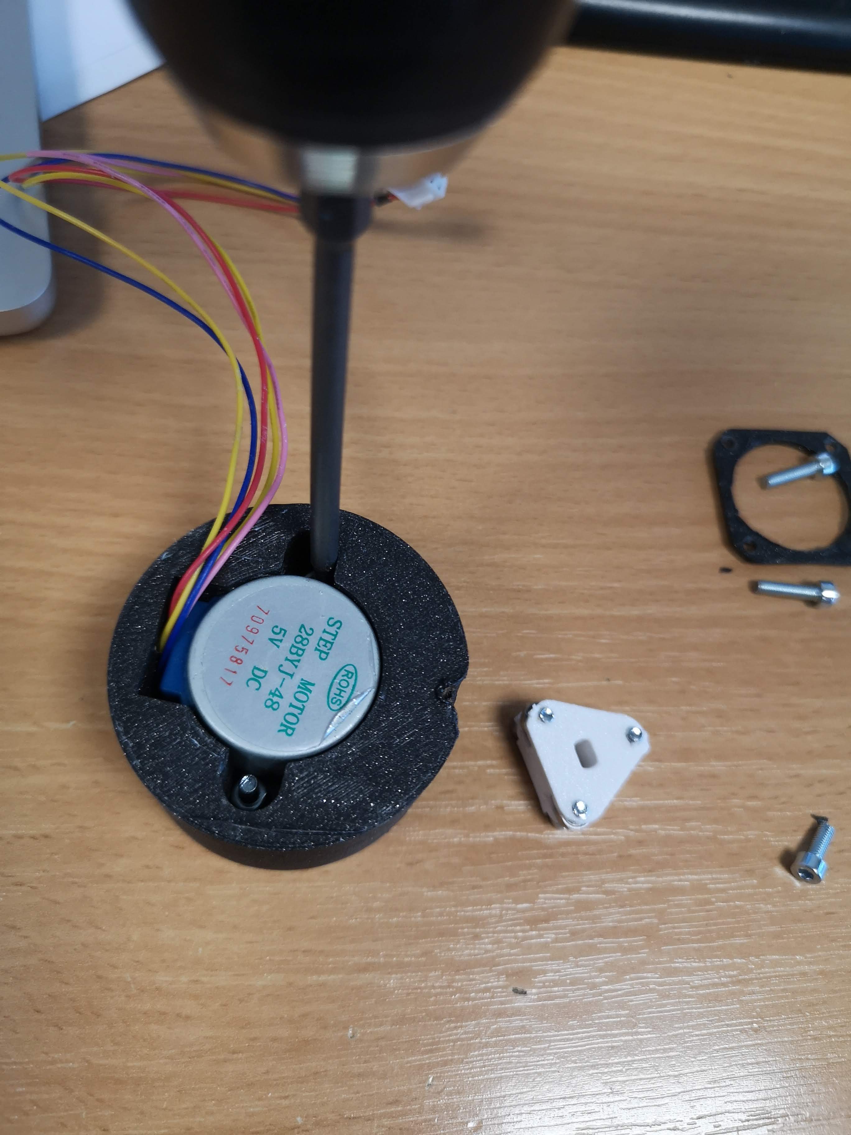
Add the perestaltic head to the motor shaft
Add a tube that fits the assembly (e.g. 5mm silicon), mount zipties to the ends of the inlet/outlet, so that when rotating the motor, the motor, the tube won'T run away
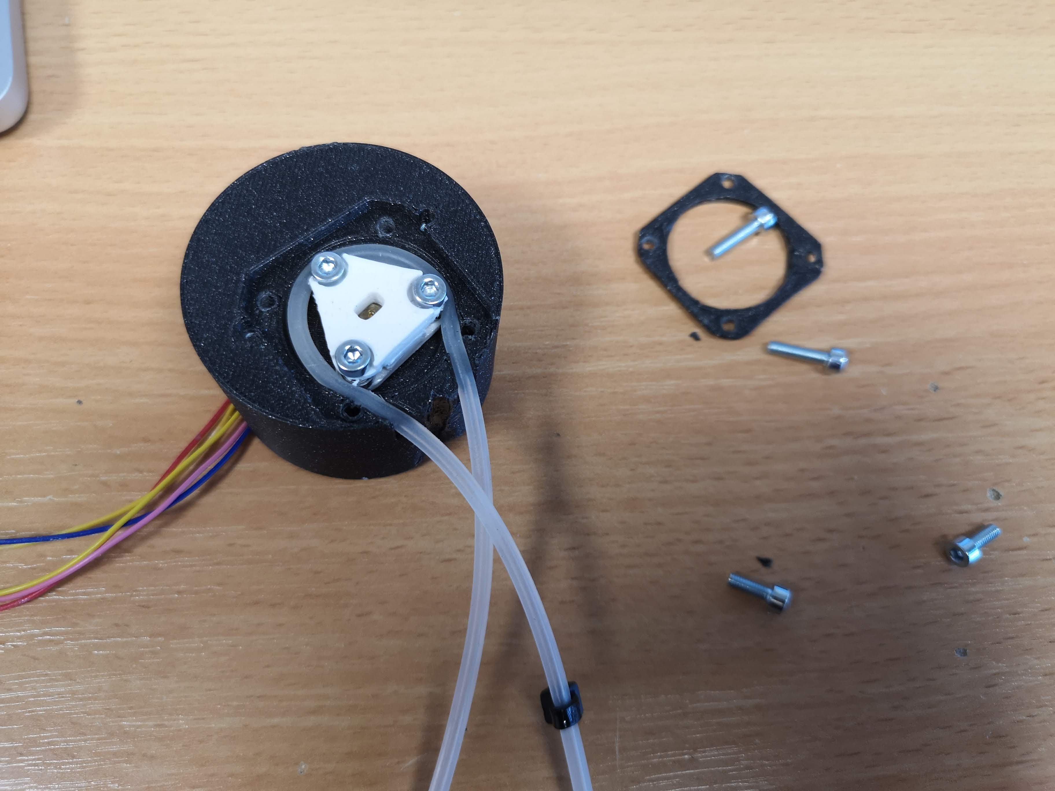
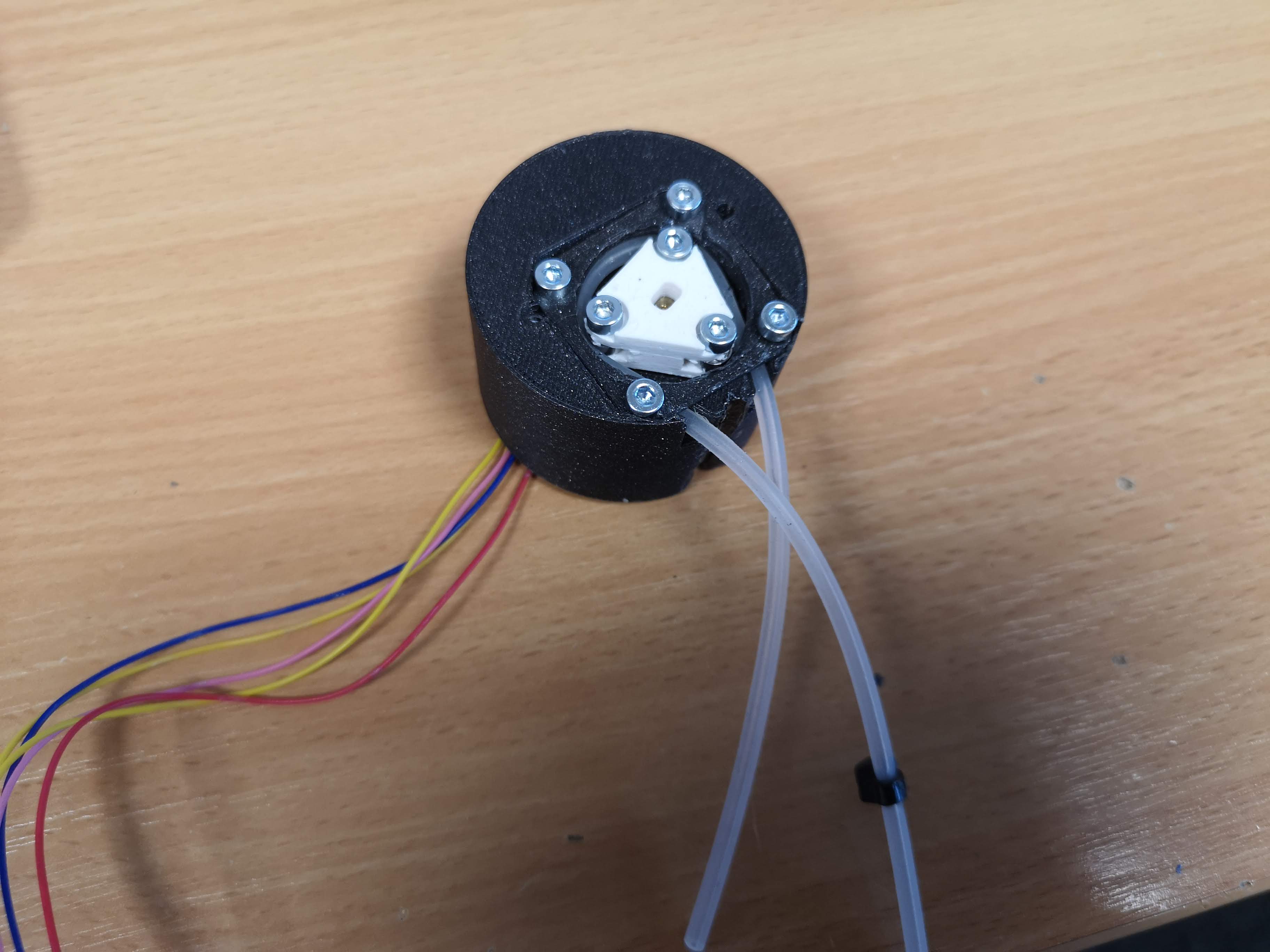
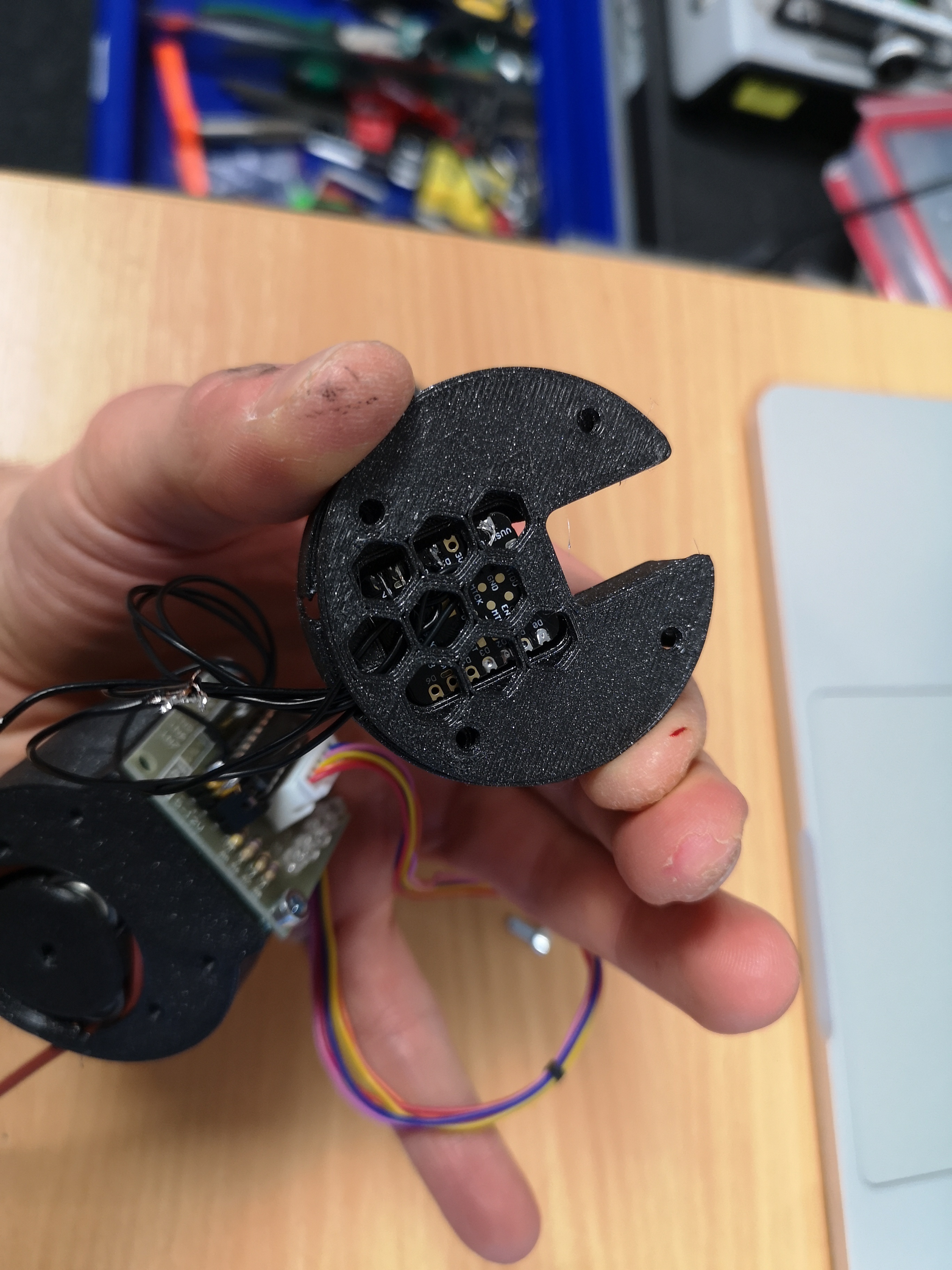
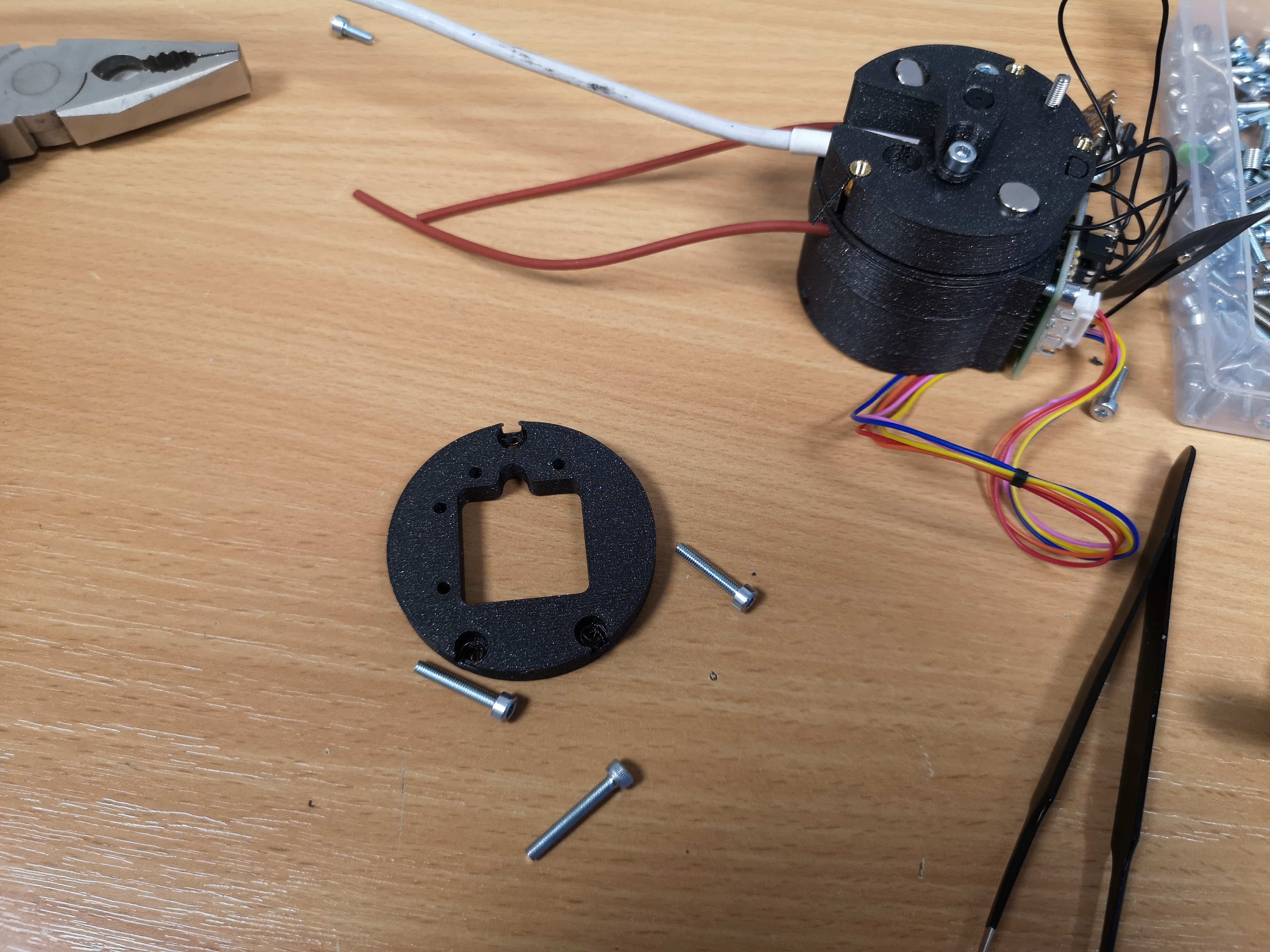
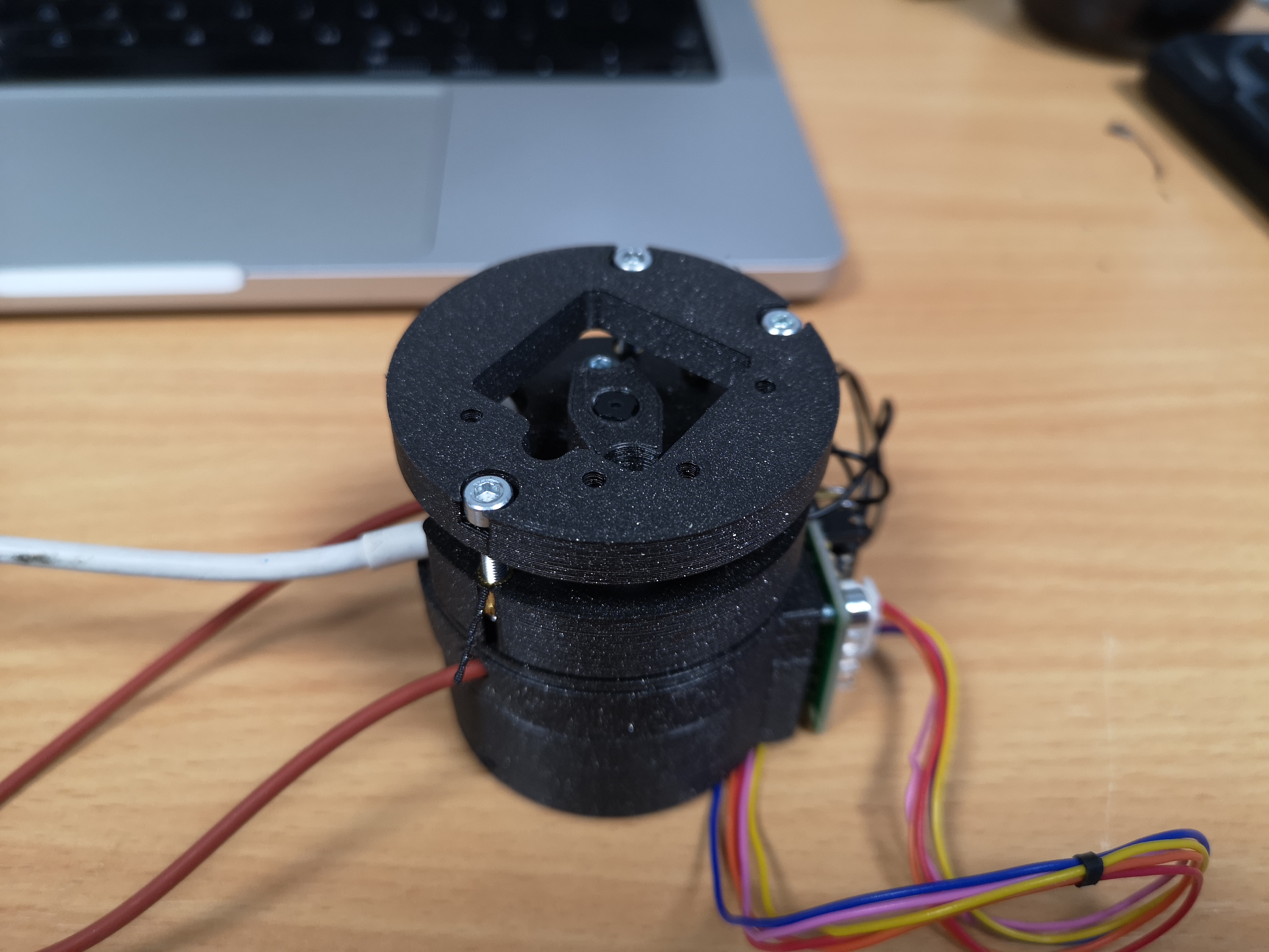
Add the lid and fix it with M3x12mm screws;
The wiring should look like this. Follow this tutorial for the wiring; You can choose almost any pin configuration. The code we will use later can be found [here]:
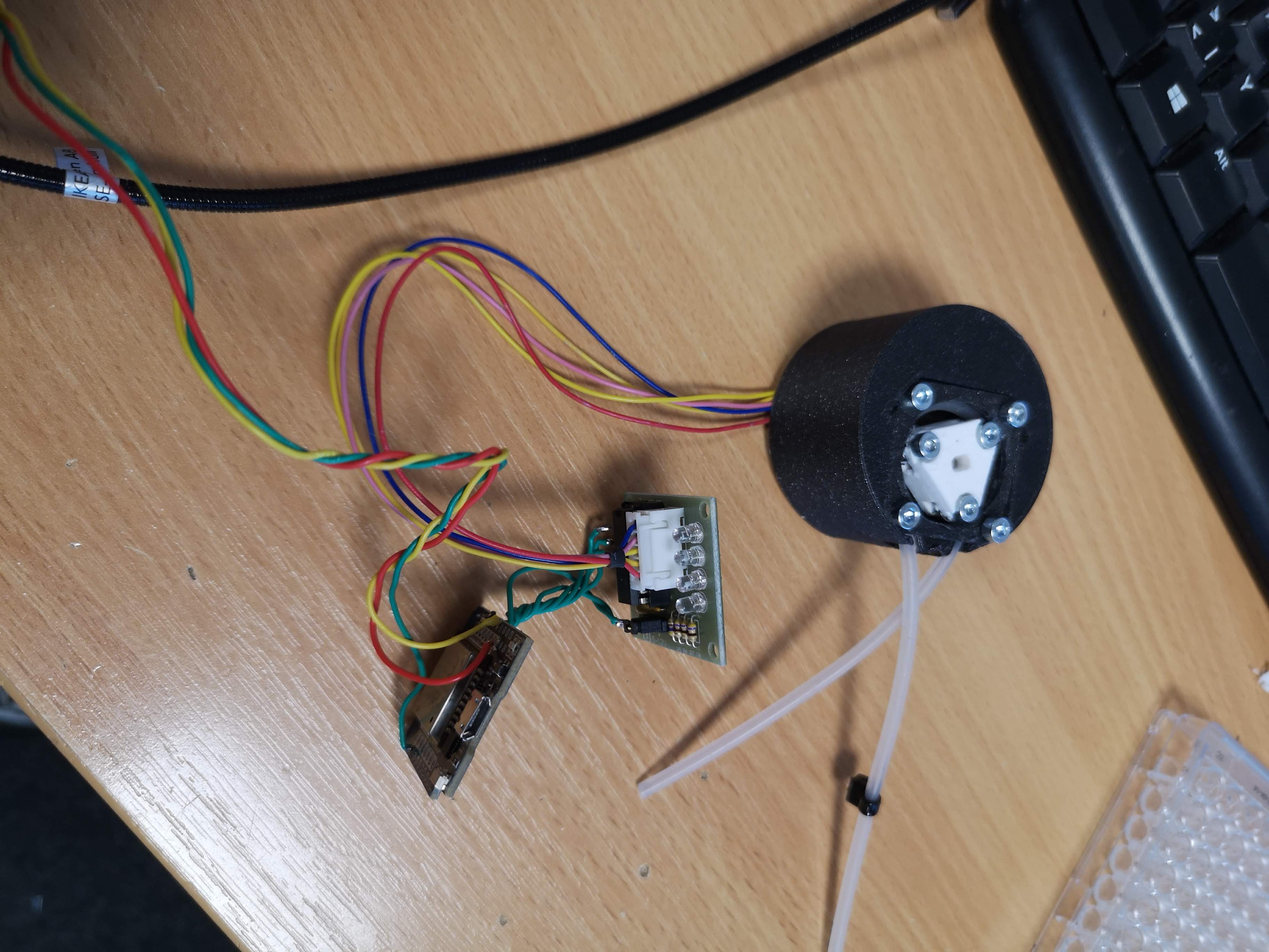
The motor will get the PWM signal from the camera and controlls the motor's rounds per miniute acoordingly: The in1-4 pins on the ULN2003 can be 32,25,22,27 as stated below. The "analogIn" was chosen to be 4.
:::INFO We have implemented the stepper code in the XIAO firmware as well. Please have a look here https://github.com/Matchboxscope/matchboxscope-simplecamera/tree/matchboxscope and watch out for the accelstepper code. File an issue if you need more information :::
In code:
#include <Stepper.h>

const int stepsPerRevolution = 2048;  // change this to fit the number of steps per revolution

// ULN2003 Motor Driver Pins
#define IN1 32
#define IN2 25
#define IN3 22
#define IN4 27

#define analogIn 4

// initialize the stepper library
Stepper stepper(stepsPerRevolution, IN1, IN3, IN2, IN4);

void setup() {
  // set the speed at 5 rpm
  stepper.setSpeed(10);
  // initialize the serial port
  Serial.begin(115200);
}

void loop() {
  // read analog value from the potentiometer
  int nAverage = 20;
  long valSum = 0;
  int val = 0;
  for(int iAverage = 0; iAverage<nAverage; iAverage++){
    // we use PWM, so we have to create some kind of mean..
    valSum += analogRead(analogIn); // 0..4095

  }
  val = (float)valSum/(float)nAverage;
  Serial.println(val);

  // if the joystic is in the middle ===> stop the motor
  if (  (val > 2000) && (val < 2100) )
  {
    // STOP
    Serial.println("STOP");
    digitalWrite(IN1, LOW);
    digitalWrite(IN2, LOW);
    digitalWrite(IN3, LOW);
    digitalWrite(IN4, LOW);
  }

  else if (val >= 2100)
  {
    // map the speed between 5 and 500 rpm
    int speed_ = map(val, 2100, 4095, 1, 15);
    // set motor speed
    stepper.setSpeed(speed_);

    // move the motor (1 step)
    stepper.step(1);
  }

  // move the motor in the other direction
  else
  {
    // map the speed between 5 and 500 rpm
    int speed_ = map(val, 2000, 0, 1, 15);
    // set motor speed
    stepper.setSpeed(speed_);

    // move the motor (1 step)
    stepper.step(-1);
  }
}
Make sure the motor runs freely (for this, simply connect the motor driver board to the ESP, e.g. following this tutorial and try a sample code for teh arduio IDE)
Hide all the cables
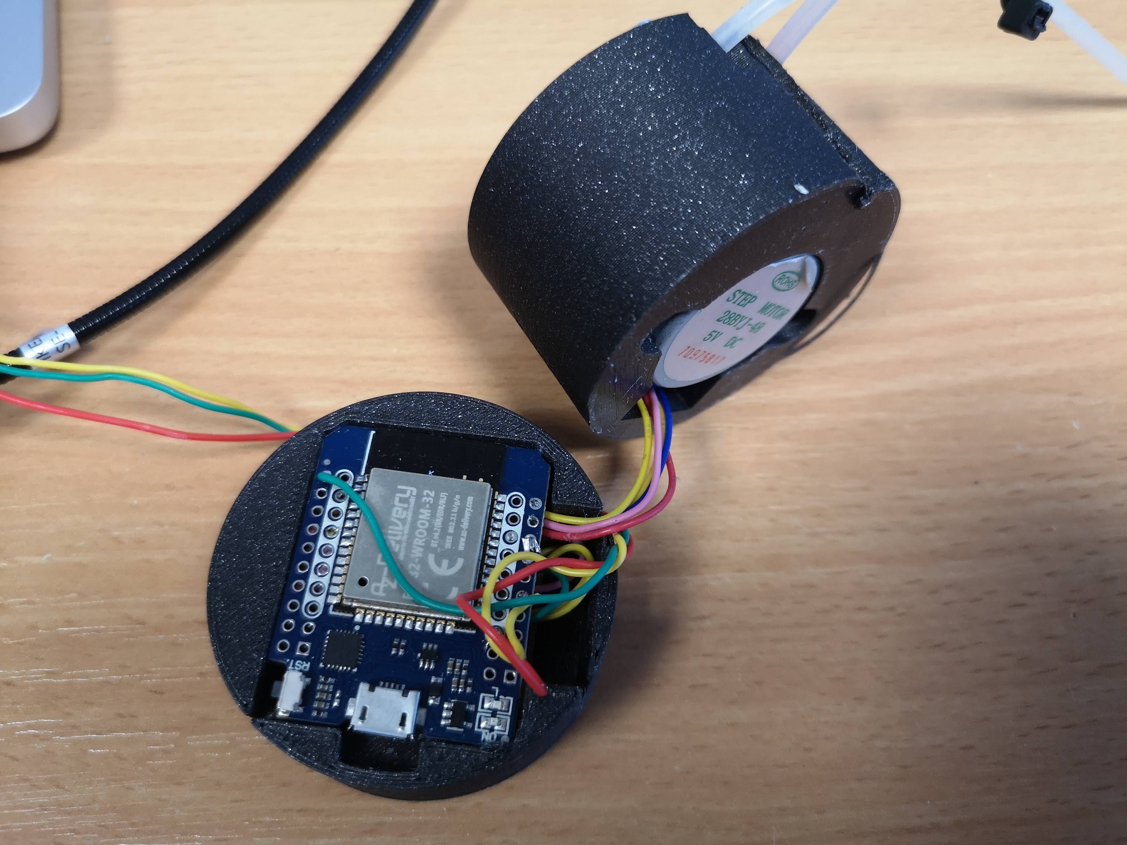
Put it close together, organize the wires and tubes
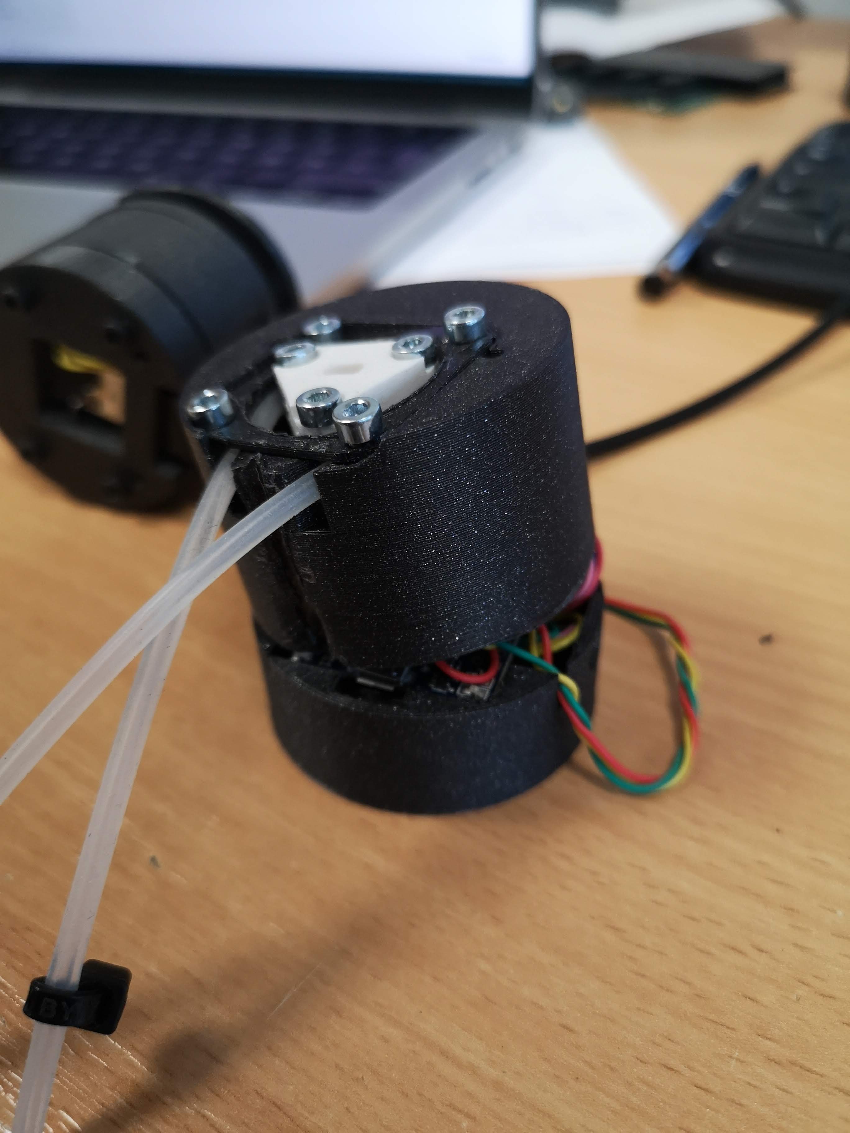
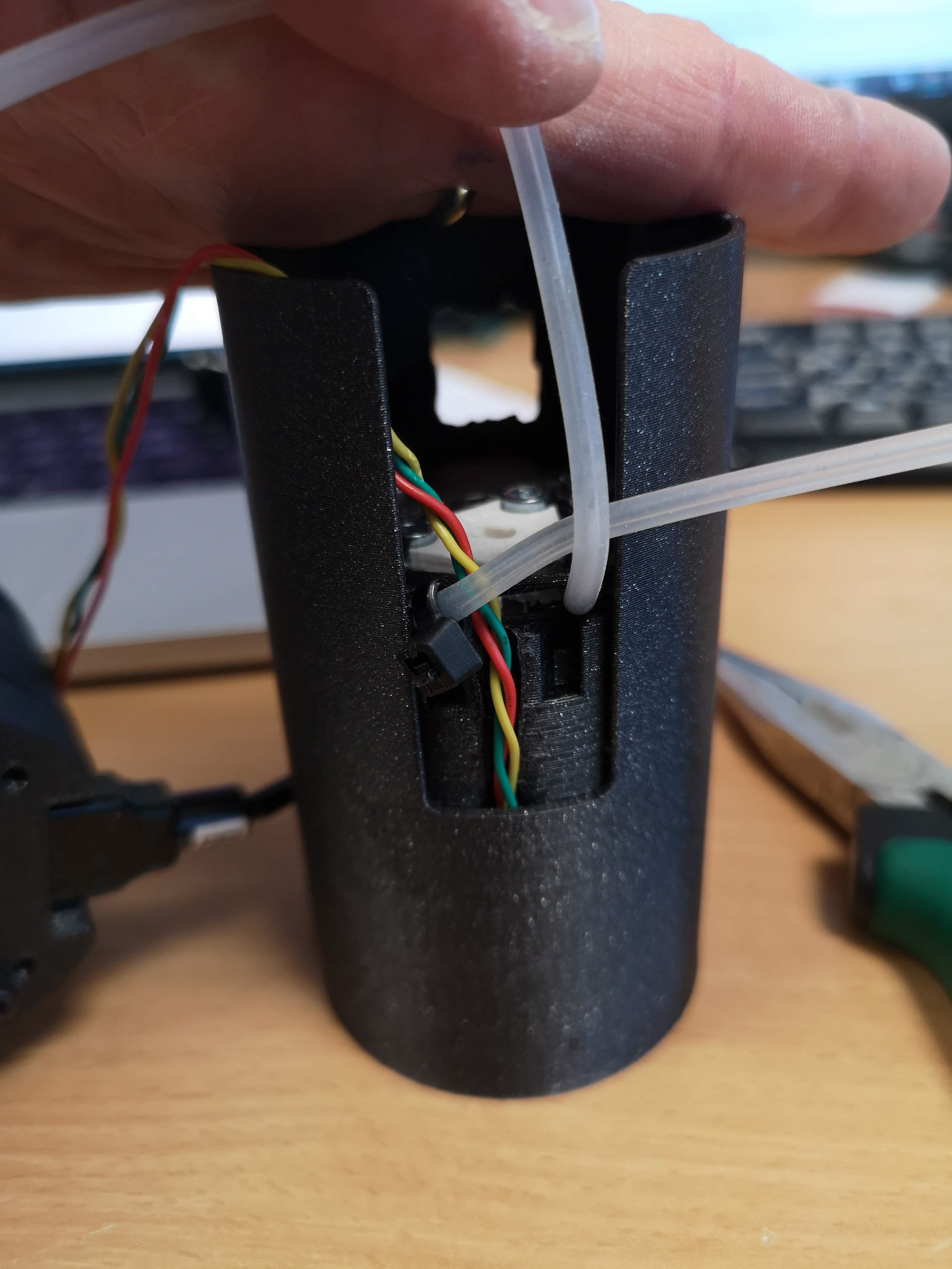
Add the tube and make sure the wires are leaving the assembly like this:
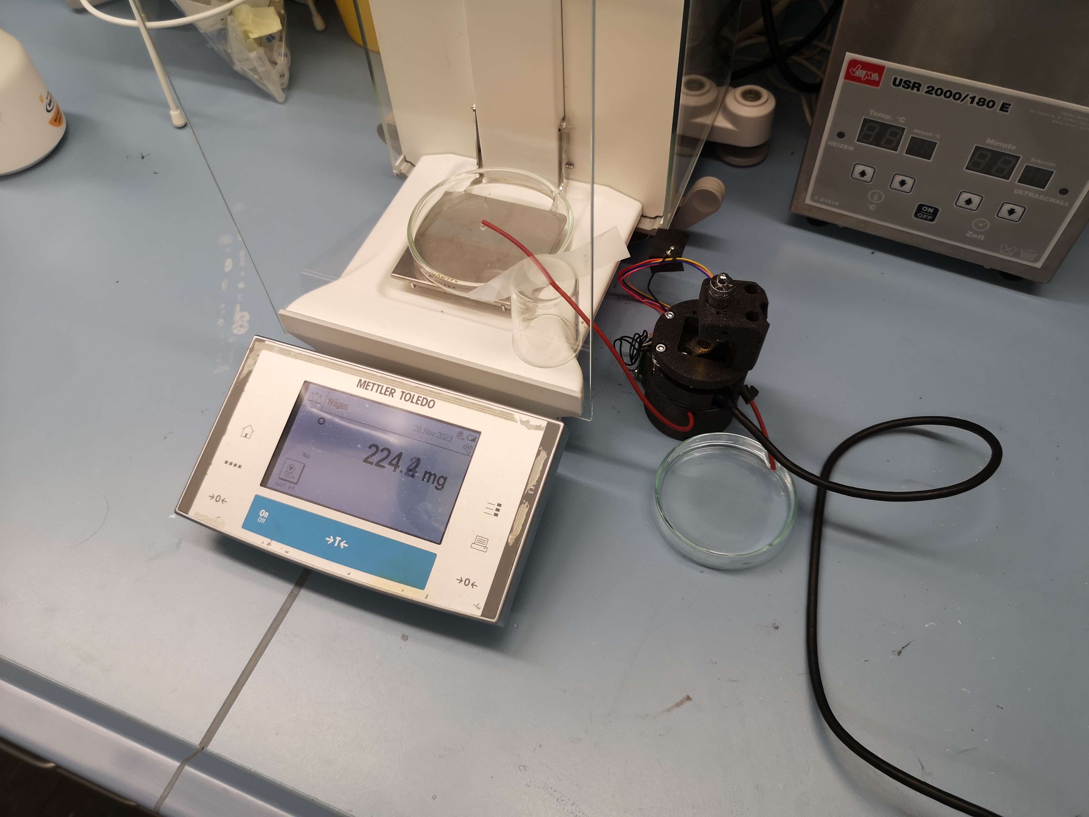
Determination of the Flowrate
# this is to compute the mean and stdv of the flow-reate of the low-cost pump
# measured by weighing the water that was pumped at 1000 steps/s
import numpy as np
mArray = np.array((860, 940, 850)) # ml/min
print(f"Flowrate: %f +/-  %f ml/min", np.mean(mArray), np.std(mArray))
#Flowrate: %f +/-  %f ml/min 883.3333333333334 40.2768199119819
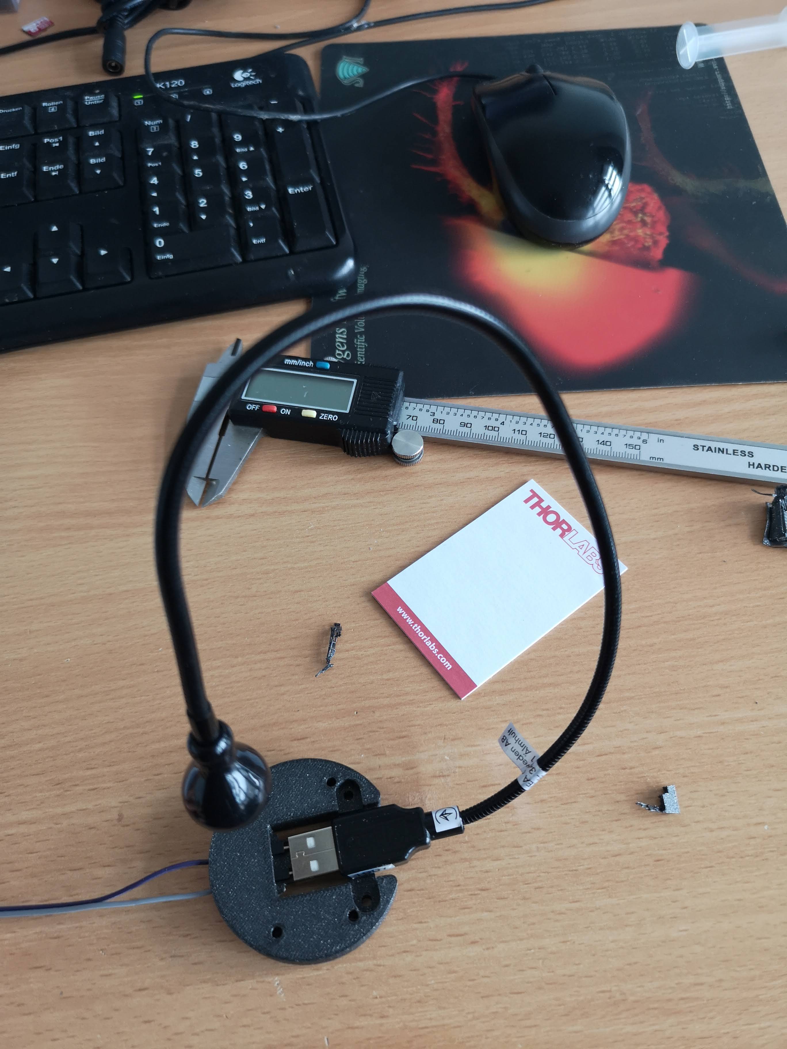
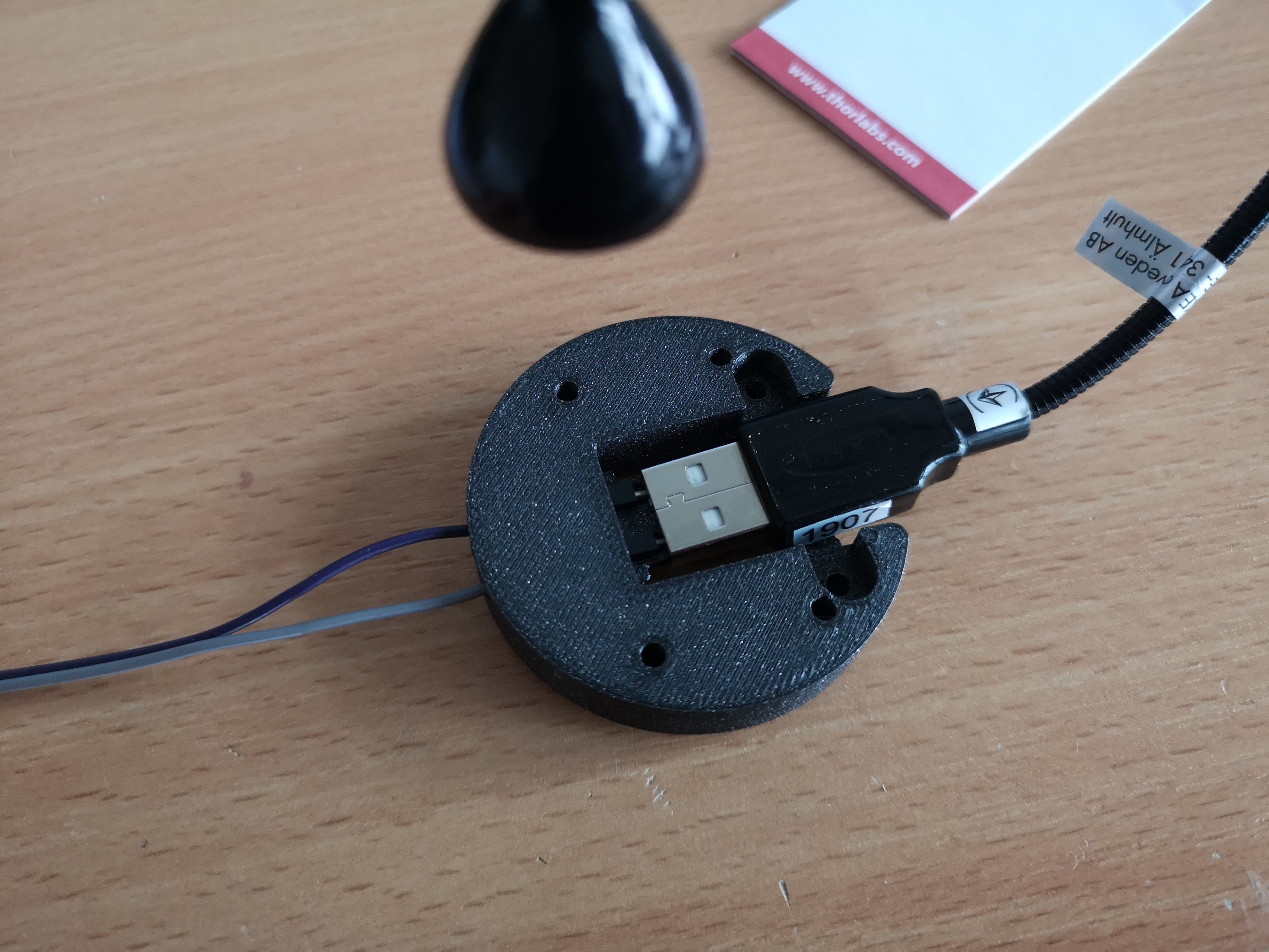
Some thoughts on the Ikea Lamp
This is inspired by the https://www.thingiverse.com/thing:5167475 design, where Dupont cable were added to a 3D printed assembly in order to mimic a female USB plug. To be honest, it's much more straightforward to simply by a female adapter and solder it to the board using some wires - but: I didn't have one, so I created this layer for the lamp. It wasn't straightforward to add the ikea lamp - so: WARNING Better buy one of these and solder it to the ESP 5V/GND :)
And all mounted together:
Done!!!
ESP32 Xiao-based Planktoscope Mini
This is a newer version of the Planktoscope Mini that uses the Seeed Studio Xiao Camera module. The benefit: We don't need a secondary PCB to control the Motor since we have more available GPIO pins! Yay!
Showcase
Assembly
Printed Parts
All files can be found in the release here: https://github.com/Matchboxscope/Matchboxscope/releases/tag/PlanktoscopeMini
BOM
- 2mm Silicone Tube with high flexibility
- 28byj-48 + ULN2003 driver
- Wires
- DIN912 Screws
- Springs
- Seeed Studio Xiao Sense
- Microfluidic chip
Software
The Anglerfish Software here: https://github.com/Matchboxscope/matchboxscope-simplecamera/tree/matchboxscope has the abbility to control the stepper driver via the ULN2003.
More information here: https://github.com/Matchboxscope/matchboxscope-simplecamera/blob/matchboxscope/main/main.ino#L33 and here: https://github.com/Matchboxscope/matchboxscope-simplecamera/blob/matchboxscope/main/camera_pins.h#L90